List of “good” inverters please

The friendliest place on the web for anyone who enjoys boating.
If you have answers, please help by responding to the unanswered posts.
Had a Hart on our previous boat, when it failed, I replaced it wit a Magnum, and was very happy with it, and no problems. We have a Magnum on our current boat, still happy, and no problems (knock on wood).
 
With any inverter, make sure that the area around the inverter, especially the ends with openings are free of any combustible items. Why our inverter meltdown did not start a fire on our boat.

Lessons learned:

Install a smoke detector above the inverter. It would go off immediately instead of whatever time for the smoke to reach the ceiling mounted smoke detector.

Install a heat shield around the battery disconnect. Ours was distorted by the heat generated by the self destructing inverter and stuck in the open position. Installing a disconnect outside the inverter compartment would result in longer battery cables. A better option may be a solenoid instead of the rotary disconnect switch, protected with a heat shield, that could be controlled from outside the compartment. And maybe shut off by a thermister/relay.

Having a fan venting the inverter compartment expelled most of the smoke outside. Smoke came back in through the windows. If a smoke detector had been installed in the inverter compartment, as mentioned above, we may have awaken sooner and closed the windows.

Having the second inverter as backup allowed us to continue our summer, even though we smelled like smoke.
 
I am happy with my inexpensive, 3kw true sine wave Ebay inverter that has worked flawlessly 24/7 for the last two seasons. I built an automatic switching circuit for our fridge's power that changes it from dock to inverter when dock is absent.

These inexpensive inverters including the much mentioned Magnum are marketed for vehicles meaning that there is no grounded conductor. Today I ordered a Hammond 3KVA isolation transformer new from Ebay with the delivered price of $200 for added safety. This addition will raise my total cost to provide safe inverter power to around $500.
 
I take it the iso xfmr is going at dock power line and not the inverter output line?
 
NO! It is going to be connected to the inverter’s output. Inverters that I am aware of sold for vehicle usage cannot have one leg of the outputs tied to ground as is found in house wiring.
 
I'm a miserable 'oul git and everybody knows I'm as tight as a ducks ass.
I bought a Doxin 10kw inverter for 200 Euro's.
We only use it while cruising to power the dishwasher and washing machine as with two alternators feeding it under way is no problem.
When stationary we use a 25 Euro Doxin 2KW inverter to power the freezer.
Victron were recommended to drive the freezer to me by an 'expert' who calculated the size power output etc. It broke down as did its replacement (we discovered they were built in India) I repaired them and sold them.
Consequently my opinion of experts' is 'Ex' is a has been and a 'spert' is a drip under pressure.
I'm with Trump and wish to promote home trade but I had no luck with alternatives..
 
As a private businessman I always try and support other private businesses from my own country over corporate giants wherever possible. That of course is my own personal opinion, I hope were gentlemen enough to agree to disagree.
 
Last edited:
I do not agree with your opinion.


It would be helpful, then, to understand why most large scale systems have earthed neutrals and also why using ground referenced supplies introduce a new risk for shock potential.
This added risk does not exist when both sides on the line are floating off ground.
Further, the potential benefits of isolation transformers are negated when one earths one of the output lines.
What i call “large scale” installs require earth tied feeds to mitigate two kinds of faults. First, it provides a path for lightning currents. Second, it reduces the damage caused by primary to secondary faults in step down distribution transformers. Either of which would otherwise likely cause severe damage downstream.
Small scale installs don’t have those two threats, and so have no benefit from “one side grounded” designs. In fact, doing so increases human shock potential. GFCI ‘s do help though.
 
I should add that there are multiple reasons why isolation transformers ARE a good idea, when correctly placed. I think more should be used on boats. Firstly, they block common mode currents. Most lightning based surges have very significant CM spike content. The IT blocks them from entering ships power systems.
Second, the IT that has a low line primary tap can be used to boost a 208v shore feeder to the correct 240v.
Third: leaving the output floating removes most all the line thru human to ground shock risk.
Fourth. So called galvanic currents essentially reduce to zero. U/W metals and nearby swimmers will thank you.
 
To put a fine point on this: yesterday and again today i will be doing some testing in a 800kV lab in Toronto. Whilst my test specimens are being subjected to this mayhem, i am sitting with me laptop about 8 feet away; blast wall in between. My dell is being charged and is being fed thru a isolation transformer. [emoji2]
 
It would be helpful, then, to understand why most large scale systems have earthed neutrals and also why using ground referenced supplies introduce a new risk for shock potential.
This added risk does not exist when both sides on the line are floating off ground.
Further, the potential benefits of isolation transformers are negated when one earths one of the output lines.
What i call “large scale” installs require earth tied feeds to mitigate two kinds of faults. First, it provides a path for lightning currents. Second, it reduces the damage caused by primary to secondary faults in step down distribution transformers. Either of which would otherwise likely cause severe damage downstream.
Small scale installs don’t have those two threats, and so have no benefit from “one side grounded” designs. In fact, doing so increases human shock potential. GFCI ‘s do help though.


I am not going to dwell on AC distribution methods other than to briefly mention the perils of floating systems such as the three phase deltas commonly found in power distribution. Back it the days of yesteryears, linemen worked with bare hands on high voltage wiring. They could because the system was ‘floating.’

But things changed forcing linemen to use insulated gloves and tools because there could be no guarantee that a tree branch was not touching one of the so call floating wires allowing ground current to flow and exposing the lineman to dangerous voltages. Another comment on floating systems is they are affected by static voltages that can build quit high. Because distribution lines are long, the capacitance to ground can be large storing high amounts of energy. Stored static energy in joules is 1/2(C*V^2). Note the function of V squared. But enough of power distribution. It has been a long time since I was a young electrical circuit design engineer.

Now to inverter issues! Inverters make AC, pseudo or true sine waves and DO NOT HAVE FLOATING OUTPUTS! OK....maybe some weirdo can put together a circuit that will, not the case though for the inverters advertised for vehicle usage.

I have several utility outlets for general use that I want energized while on dock power or my inverter. But the grounded conductor MUST be isolated from the inverter. The grounded conductor and the grounding conductor are married together at either the dock’s power pedestal or at a load center used for the dock’s power. A grounded conductor imposes a SHORT CIRCUIT on the inverter’s output. The inverter output must be isolated from the dock’s ground otherwise, it will destroy the inverter. Sure, I could use an elaborate relay scheme to isolate the problem. I could also use the inverter as an isolated power source rather than dock power.

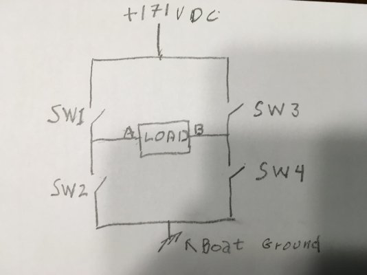
So how does this happen? Inverters use what is known as an H bridge which I will explain using my sketch. The load in the center of the H bridge while the top of the bridge is connected to an internally developed voltage about 171 VDC. The bottom of the bridge is connected to the boat’s ground that is connected of course the the batteries’ negative return. The inverter’s object is to ‘make’ 120VAC RMS @ 60Hz. The peak voltage in a sine wave is equal to the RMS voltage times the square root of 2, close to 170V in this example. Because a voltage drop across the switches happens when the circuit operates, another volt or two most likely is needed from the DC supply to make the 120VRMS. The so called load shown also contains filters to make a sine wave. I describe an ‘on’ time for the switches which is the time period where the load is pulsed needed to make AC. The simplified circuit explanation is to help understand how the H bridge works.

The circuit requires two switches to close at the same time and then alternate with the opposite switches. Consider SW1 and SW4 closed. Current will flow from the 171VDC (top of bridge) through SW1, the load and SW4 back to then power source via the ground connection. This current is pulsed for 8.3 milliseconds equal to 1/2 of the 60Hz sine wave. The other half of the sine wave begins by opening SW1 & SW4 and closing SW3 and SW2 . The current now flows in the opposite direction through the load. Again, the conduction time is the same as current flowed in the other direction but pulsed

The points A & B represent the electrical connections one would find in a common wall outlet. But neither can be grounded! Consider placing a ground at point B. When SW3 closes it creates a SHORT CIRCUIT on the 171VDC power supply! The same will happen if a ground was placed at point A. SW1 would then short circuit the 171VDC supply

There are NO floating voltages in an H Bridge! Each side of the load is either close to 170V or ground potential. I want to be able to connect my inverter to wall outlets automatically after losing dock power. Why bother with complex circuitry when I can just use a transformer and be done with it. Can others do things differently? Of course. I got stung a couple of times operating my davit crane in wet weather powered from my inverter. An isolation transformer will prevent that. So that should provide a basic understanding of what goes on in an inverter.
 
WOOPs My sketch got lost
 

Attachments

  • 8A21C279-B2A3-4811-8C14-1E64E6CC5BED.jpg
    8A21C279-B2A3-4811-8C14-1E64E6CC5BED.jpg
    46.9 KB · Views: 29
I've installed an isolation transformer on every boat I've owned. Every boat should have one installed.

Every thing DiverDave mentioned is accurate.

Isolation transformer equipped boats have no difficulty plugging into marinas that have installed the ABYC E-11 mandated ELCI and GFCI breakers. I sold a lot of Isolation Transformers right after Poulsbo Marina installed the ELCI breakers.

An isolation transformer equipped boat does'nt have to be concerned with shorepower reverse polarity either.
 
Last edited:
I understand that. These inverters need an iso transformer in your use case.

I think a bunch of those old linemen are missing limbs.
 
Foggy. We rather skipped over one question. Ate we talking about your boat that has a earthed neutral? I suspect not. But when ur inverter is in use, how is it seeing a grounded “neutral” ? Is not a DPDT switch used to remove both sides of shore power? Also, on the shocking davit. Is the exposed metal not earthed?
 
Hi Dave-

To the quick: Problem occurs ONLY when connected to an external power system, a dock’s power if one of the inverter’s output wires is connected to the boat’s neutral. The inverter can ONLY be connected to the boat’s neutral conductor IF not connected to an external power source that complies with the National Electric Code.

My boat’s wiring follows the same wiring requirements regarding grounds as one would see in a building. The neutral which is by code colored white is isolated from the boat’s grounding system which has the 12v returns (negative battery post) from the grounding (green) conductor. The ground and grounding conductors get married together at the power source which is the dock pedestal OR carried further to the the main power load center.

When one of the inverter output connections is tied to a boat’s neural wire which is connect to ground at an external power source ....neutral and ground tied together this places a dead short right in the middle of the inverter’s H bridge. Either a circuit breaker/fuse will interrupt the 12vdc circuit that powers the inverter or one of the inverter’s internal H bridge’s switch (the ones connected to the 170vdc power) will fail open.

Yeah, I know, confusing.
 
Ok. I think i have that envisioned. But there is no switch to entirely isolate the inverter when on shore power?
 
YEAH!!! That is the problem. At present I use a relay but I want to extend the inverter to multiple outlets and feel the safest way is with a transformer. And by the way, I did consider using main transformer to power the entire boat. Size and weight plus trying to find a mounting location prohibited doing that. And of course, you are most certainly correct to recommend such transformer!!!!!
 
The iso transformer output would be removed from shore power L and N when not in use?
 
No, I plan to connect the inverter directly to the transformer whose secondary will have one leg tied to the boat’s grounded conductor. And I am not the only guy using inverters with this problem.
 
So, if a reverse polarity shore power is attached, we would expect an immediate high current fault?
 
No, I plan to connect the inverter directly to the transformer whose secondary will have one leg tied to the boat’s grounded conductor. And I am not the only guy using inverters with this problem.

Foggy
I was perusing Calder's recommendations for ITs and inverters. Rather than quote from him - Would your setup be in agreement with Calder?
 
Any rec's for a small (<1000 watts) inverter that will NOT be connected to the boat AC systems? I have a need to run my electric E-Propulsion outboard charging brick at 400 watts....Everything else on the boat is 12V so no need for a "House" inverter....
 
119 posts and no “good” inverter yet?
Must be very interesting though.
 

Latest posts

Back
Top Bottom