help with nmea 2000

The friendliest place on the web for anyone who enjoys boating.
If you have answers, please help by responding to the unanswered posts.

magna 6882

Guru
Joined
Apr 20, 2020
Messages
695
Location
USA
Vessel Name
Intrepid
Vessel Make
North Pacific/ NP-45 Hull 10
hello all
I have been having some gremlins with my network since the boat was new. Depth finder would stop working once in a while for a few minutes and then would stop about 25 percent of the time then on this last trip auto pilot would show a loss of speed sensor. Since there are no boat repair shops even answering there phone i decided to try to take on troubleshooting myself.
I purchased a n2k meritron meter and a nmea 2000 to usb adapter for connection to a computer.
What i am confused about is the connection of these devises.
Can i just add 2 tees to the backbone and add the terminal resister?
Can a tee or drop remain in the system with no connection once i remove the meter?
 
N2K is simple, but strict. Deviate from the specs and you get gremlins.

It must be a network with two ends, with a terminator at each end. Drops come off that network using tees. One device per tee. Power must never be provided from more than two sources and it MUST be the same voltage (no voltage drop between different points).

There are additional ways to bridge separate networks, but each will still need to be a bus network with tees.

Maretron's software is fantastic for this. Both the builder software and the analyzer. The build software will let you model your network and tell you if it's up to specs.

https://www.maretron.com/products/N2KBuilder.php

The analyzer will let you see what is on the network, provided you're using either their USB or ethernet interfaces. I use the IGP100 interface over ethernet (which is overkill unless you have things that are going to remain connected via ethernet). The USB100 allows connecting just one PC, and is less expensive.

https://www.maretron.com/products/N2KAnalyzer.php
https://www.maretron.com/products/ipg100.php
https://www.maretron.com/products/usb100.php

To use either of the interfaces you'd need to add a tee into the network somewhere and connect to that. That or if you've got a free port already open on a multiport box or an empty tee.

Tees have three connections, one on each side to extend or terminate the network and the other, a drop port, to connect a single device. You CANNOT string multiple tees off a drop port. Well, physically you CAN but you introduce network problems due to how the signal expects to propagate over the wiring.

Your network has to have a starting point somewhere, with a tee and a terminator in it. You can daisy-chain multiple tees into each other and then use a length of cable in-between the tees to extend the network. From each tee you can have EITHER one device OR a multiport expansion box.

If you make the mistake of pulling the cable the wrong way (they have male-female ends) then use a gender-changer to correct the mistake (or pull the cable again correctly). DO NOT USE TEES to correct mistakes.

A drop from a tee to a single device should be as short as possible and your total network drop length (totaled from all of them) should not exceed 78 meters. The backbone itself should also be as short as possible and not exceed 200 meters. The cables are relatively cheap. It's better to just get the right length of cables rather than coiling up excess.

Power is best applied near the physical center of the network to avoid voltage drop being a problem on a long network with a lot of devices. It doesn't "have to be" if the network isn't very long. But for a long network if you power it from one end, the devices at the other might not see enough voltage to operate reliably.

Once you reach the other end of the backbone there would be another tee to the last device and a terminator.

So first make sure you understand how your network is physically laid out.
 
Last edited:
Very helpfull post. So if i understand correctly the tee i add to connect the meter can remain unused for any future testing or should i remove the tee after testing?
 
If the network is otherwise reliable it wouldn't be 'harmful' to leave a tee inserted. But they're easy to add/remove so it's up to you.

I'd start by using the Builder program to map out what you've got. Make sure the basic design passes.
 
Doesn’t the T have to be terminated if not connected to a device?

Tom
 
Doesn’t the T have to be terminated if not connected to a device?

Tom


No, definitely not. There must be exactly two terminators, no more and no less, one each located at each end of the backbone. A quick check is to measure the resistance across the two data lines. It should be 60 ohms. That tells you there are two terminators. But it doesn't tell you where they are located, so you still need to verify that. But if you see 120 ohms then you one have one terminator, and if you see 40 ohms or lower then you have three or more.


Excellent guidance from WKearney99 above.


One question for Magna, you said


"Can i just add 2 tees to the backbone and add the terminal resister?"


You shouldn't be adding or removing terminators unless 1) they were not installed correctly in the first place, or 2) you are extending one end or the other of the backbone. That said, I vaguely recall that one of the tests you can do with the Maretron Meter is to connect it in place of a terminator? Maybe that's what you are talking about?
 
In my experience, flaky operation is rarely an underlying cabling or electrical problem, and usually some sort of errant operational (aka software) problem.


Once you get N2KAnalyze running, take a look at any device's transmitted PGNs, and look at how frequently you are seeing Address Claim PGNs. N2KAnalyze does a periodic Address Claim, but if you put it in Listen Only Mode, it will stop and you should not see ANY Address claims. They should only happen when there is a network configuration change, e.g. plugging in a new device, or powering a device on or off. If they are happening all the time then something it wrong and needs to be fixed. Address Claims are very disruptive and cause devices to stop what they are otherwise doing to complete the claim process.


Once that's clear, you can look at the transmitted PGNs from the sensor that keeps disappearing. If its PGN transmissions are pausing, then the issue is with the device. If the transmissions continue uninterrupted, then it's the receiving device that's getting confused.


Unfortunately, N2K is very poorly specified leaving many operations open to different interpretations and different approaches, some of which are incompatible and/or trip up what other devices are doing or expecting. The probability of adverse interactions grows exponentially as you add more devices. But it's clear that now 22 years into it, NMEA isn't going to fix or address any of these issues, so you just need to muscle through and figure out how to cobble together something that works well enough.


For the first 5 years I was using N2K, I built progressively larger networks, culminating in 2014 with a boat where the design rule was 100% N2K and 0% NMEA 0183. That failed, and I have since been building progressively smaller and smaller N2K networks, and using other more robust standards where possible.
 
The network on mine was screwy, I had to rearrange it a fair bit. Now it ends down in the engine room, snakes up to the lower helm, goes up to the flybridge and then back up to the mast at the stern. Drops come off for the depth sender in the engine room, forward for a heading sensor and then two go up the mast for weather and satellite compass. Power is at the mid-point in the flybridge. I'm less than pleased at the mess of tees I have in the lower helm and may swap them out for at least one Maretron multiport, but the tees do the job ok.

A side note, be careful about doing device firmware updates over N2K. I had a lot of trouble updating two Maretron DSM-410 units over the bus. For two reasons, one being mis-matched firmware versions using their updater and the second being the bus was "too busy". I had to simplify the network to get one of them updated. The other got bricked (by Maretron using TeamViewer remotely) and has to go back for an update.
 
For the first 5 years I was using N2K, I built progressively larger networks, culminating in 2014 with a boat where the design rule was 100% N2K and 0% NMEA 0183. That failed, and I have since been building progressively smaller and smaller N2K networks, and using other more robust standards where possible.

The K.I.S.S. design principle always has merit.

If 4 decades dealing with tech products has taught me anything, NEVER assume a product will work in all scenarios, even if it "should". Perhaps even ESPECIALLY if someone that hasn't actually done it claims that it should.
 
Once you get N2KAnalyze running, take a look at any device's transmitted PGNs, and look at how frequently you are seeing Address Claim PGNs. N2KAnalyze does a periodic Address Claim, but if you put it in Listen Only Mode, it will stop and you should not see ANY Address claims. They should only happen when there is a network configuration change, e.g. plugging in a new device, or powering a device on or off. If they are happening all the time then something it wrong and needs to be fixed. Address Claims are very disruptive and cause devices to stop what they are otherwise doing to complete the claim process.


Once that's clear, you can look at the transmitted PGNs from the sensor that keeps disappearing. If its PGN transmissions are pausing, then the issue is with the device. If the transmissions continue uninterrupted, then it's the receiving device that's getting confused.

I really should revisit this because I've got an older MFD12 that just refuses to see the DST800 depth sender. The depth sender is on the bus, and other devices see it, and the MFD12 does show depth/speed values when it's active, but it just will not see it during the "setup" menu in NN3D. It "used to" see it for selecting it as a source. But more recently it hasn't and I'm left thinking there might be some underlying bus congestion issue at play.

That and I keep meaning to eliminate or "dummy-down" some devices that can send data, but that is already being sent by something else. The weather unit can send GPS and heading data, as can a separate heading sensor, but both of which are superseded by a satellite compass unit that's much more accurate.

There's a tendency with upgrades and add-ons to leave things connected, for reasons like redundancy or backup, that might actually interfere with a more reliable configuration. Or to attach something "just because it can be connected" when it probably shouldn't.
 
I really should revisit this because I've got an older MFD12 that just refuses to see the DST800 depth sender. The depth sender is on the bus, and other devices see it, and the MFD12 does show depth/speed values when it's active, but it just will not see it during the "setup" menu in NN3D. It "used to" see it for selecting it as a source. But more recently it hasn't and I'm left thinking there might be some underlying bus congestion issue at play.


That and I keep meaning to eliminate or "dummy-down" some devices that can send data, but that is already being sent by something else. The weather unit can send GPS and heading data, as can a separate heading sensor, but both of which are superseded by a satellite compass unit that's much more accurate.


There's a tendency with upgrades and add-ons to leave things connected, for reasons like redundancy or backup, that might actually interfere with a more reliable configuration. Or to attach something "just because it can be connected" when it probably shouldn't.


So do you feel it’s better to disconnect devices that are not being used but left in place for a backup if needed? ie old sounders etc.

John
 
The K.I.S.S. design principle always has merit.

If 4 decades dealing with tech products has taught me anything, NEVER assume a product will work in all scenarios, even if it "should". Perhaps even ESPECIALLY if someone that hasn't actually done it claims that it should.


I agree, and would even say never assume a product does what it say is will under ANY scenario until you have seen it work. In time I will tell you about my Outback Inverter fiasco where the #2 headline feature in the data sheet simply doesn't work.....
 
So do you feel it’s better to disconnect devices that are not being used but left in place for a backup if needed? ie old sounders etc.

John


I'll be interested to hear what Bill does too. I leave backup/secondary devices on and active, and have most of the consumer devices set up to automatically fail over - at least where the consumer device has such a capability.
 
I have a PG700 heading sensor, superseded by an SCX-20 satellite compass. I have configured my plotters to use the SCX-20. I should just disconnect the PG700. The question is where to do this disconnect?

Why would this be an issue? Because what if "someone else" comes along and reconnects what they think was 'accidentally' disconnected. How could that happen? Well, this past winter "somebody" on board managed to disconnect an ethernet cable from my MFD12 and reconnect it to the Furuno hub. Apparently the RJ45 had come unplugged from the MFD12 and they thought it must have needed to be reconnected... and chose a free port on the nearby ethernet switch to do it. Thankfully this was for the secondary MFD12, not the primary. Because if it had been the primary MFD12 all hell would have broken loose when the primary's DHCP server started conflicting with the one in the new TZT16F.

Now, this should have been preventable on my part if I'd done a better job of zip tying the cabling together such that it would have been staggeringly obvious the cable CAN'T go over to ethernet switch...

Yeah, the "to do" list has had "clean up the helm wiring" for a while now.

So do I leave the heading sensor in place "in case I need it"? If so, should I unplug it at the sensor or at the drop tee in the lower helm? The sensor location is 'easier' to reach, in that it's in a closet in the starboard stateroom. But that'd also make a candidate for being reconnected if someone sees the loose cable. To get to the lower helm connection I'd be unscrewing the main panel that holds the plotters in place. Bearing in mind that this is also the place that "someone" reconnected the MFD12 incorrectly.

What about the previous GP-330B unit for GPS? It and it's drop tee is in a tedious-to-access location inside the flybridge. As in, a two day regimen of Ibuprofen after I've had to crawl in there.

Now, I could get extra fancy and set up a secondary "backup" N2K network for these devices and perhaps use a network bridge but that'd require stringing some N2K cable through a place that's already pretty congested.

Of course now that I take the time to write this it occurs to be, eff it, I should just rip them out entirely.

The new TZT16F displays have their own GPS internally, so if I lost the SCX-20 I'd still have positioning data. I'd be without heading data, but anything that killed the sat compass would probably already have me doing manual steering, so the autopilot not having heading data would be pretty low on my list.

As for backup devices, the only thing I don't have that I wouldn't mind having would be a second source for depth. The Chesapeake is pretty shallow and I've spent more than enough on prop repairs over the years. Now that Furuno has update the TZT3-series to do side-scan sonar display I might be adding sounder(s) and those could provide it. But I really don't need the old heading or GPS units and they could go.

That'd just leave wrestling with the Airmar weather unit and configuring it to stop sending redundant info. Supposedly it can be silenced but I've not done the diligence to figure out what magic combination of software and N2K interfaces will do it properly.
 
Doesn’t the T have to be terminated if not connected to a device?

No, it does not. An N2K network should always have TWO terminators, one at end end of the network and NEVER on the drop connection of a tee. TWO only, one male at one end, the female at the other.

Capped would be a good plan, if just to avoid having the marine environment conditions cause the open connection to corrode. My recommendation would be not to leave an empty tee connected, but to leave space on the backbone in an accessible location that would allow reconnecting one at a later date.

The tees are not plumbing parts. While the connectors might have the right gender to allow for certain kinds of connections, they should not be used in ways for which they're not intended. Not as gender-changers because cabling was run wrong, not as an elbow because there's not enough room to bend the cable, or hung off a cable that's already coming from another drop tee because there's now another device in that location that should be connected.

For that last scenario, where you have a need develop for another N2K device in a place that only has a drop cable running to it already, the proper solution is to add either another drop cable and tee from the backbone OR a Maretron multiport expander. NOT adding a tee on the end of a drop cable at the existing device.

Sorry if I'm being repetitive on stressing these points.


I think i understand. i have a back bone under the helm in the pilot house and if i recall it is a series of tees with cables going up to the devises. I recall thinking there was a cap at each end but i need to confirm.my thoughts were to open the backbone and add two tees.One for the new drop to the usb adapter that will be mounted permanently and a second for connecting the meter. I was thinking i could just leave the second one open once the meter is removed.
Do i just buy nmea 2000 tees and drops off amazon or is there some quality concerns and if so is there a brand i should look for. I think my current tees are garmin?
 
I've had a mix of garmin, ancor, maretron and other brands and they're all pretty similar, and most I picked up via Amazon. Though I do recall some brands point their tee in a different orientation (though I can't remember whose). I've also swapped out single tees daisy-chained to each other for 2 or 4-port units.

https://www.amazon.com/gp/product/B071JRQZGF
https://www.amazon.com/gp/product/B0915FY1MY

The combo units take up a bit less space lengthwise and need fewer screws to mount them.
 
Good point. I think i better get a look at what i have under there. I do see multi port tees and if acceptable would be cleaner to remove one tee and replace with a multi port. Thanks everyone for the help.My preference would have been to just hire someone with the tools and experience and let me get back to crabbing but everyone's schedule puts me into late September October.
 
Good point. I think i better get a look at what i have under there. I do see multi port tees and if acceptable would be cleaner to remove one tee and replace with a multi port. Thanks everyone for the help.My preference would have been to just hire someone with the tools and experience and let me get back to crabbing but everyone's schedule puts me into late September October.


Can you post a couple of pictures of what you have?


The "caps" at the ends may be the terminators. Sounds like your N2K bus begins and ends in your console, which would make things easier.


And yes, you can just crack it open at any point and insert two new tees.


As Bill points out, the index/clocking of the tees are different for some vendors, and I think Garmin is the odd man out in how they do it. If you have garmin, I'd stick with it to avoid a hassle on this front. Fisheries typically has them in stock and they are reasonably priced relative to other vendors, but still probably $20 a pop, which probably means $30 since a month ago.
 
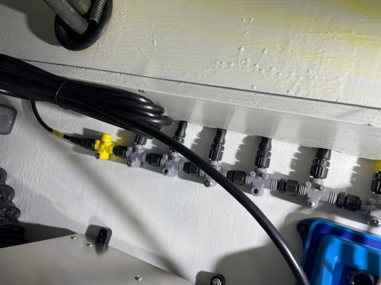
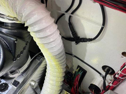
here are a couple pictures from under the helm. I see some of the back bone on the wall but am confused by the yellow tee at the end. It looks like a tee but is closed off where one would think there was an open connection. I also see a tee that is mounted above the lower helm. What do you guys think the yellow tees is?
IMG_9289.jpg

IMG_9290.jpg

IMG_9291[2644].jpg
 
In looking online i believe the yellow tee is a power isolater.
 
The few yellow ones I've used were either power taps or power isolators. The power taps would have wires coming out of the tee, to power the bus. The isolators are designed to allow powering parts of the network separately.

Like this one:
https://www.amazon.com/Garmin-010-11580-00-Nmea-Power-Isolator/dp/B00ABI6BF4

Do you have breakers that correspond to the devices that are in-between the isolated segments?
 
I am not sure where the circuit protection is for the nmea system. There is not an obvious breaker. i am thinking the connection to the yellow power isolator may be the line coming from the cummins fo engine data. The pictures i took were under the helm. I am going to pull back one of the mfds then i can look behind.
 
You *really* need a diagram laid out to help keep track of what's connected to where.

Which devices on your network can give you a list of other connected devices? That would help you determine what's out there. Then, as you disconnect and/or change the power state of things, you'd be able to see what is or isn't connected. The N2K Analyzer can certainly see them, but only from whatever segment it's attached. Presumably when everything is 'turned on' you should be able to see it all from where ever you have the Analyzer listening.

But the power isolators present make me start wondering what's really going on. That's where a diagram drawn out in the N2K builder starts to help. Or even a plain old paper and pencil sketch.

Some devices are capable of feeding 12v power out their N2K port. Basic chartplotters for small boats often have this ability. As do some outboard engines. So if you don't want that (because you have another source of power for the bus) then you'd use an isolator to keep the device from backfeeding the bus. But to have ones blocking off a running section of the bus... that raises "questions".
 
The K.I.S.S. design principle always has merit.


If 4 decades dealing with tech products has taught me anything, NEVER assume a product will work in all scenarios, even if it "should". Perhaps even ESPECIALLY if someone that hasn't actually done it claims that it should.
This is KISS?
 
Thanks everyone for giving me ideas. i got the wiring diagram attached.
 

Attachments

  • garmin wireing nmea2000.pdf
    912.2 KB · Views: 37
In looking over the drawing it looks like the transducer is connected directly to the mfd which would logically would indicated the nmea system is not as suspect as i was thinking.it looks like the mfds are also connected via a second network cable. I would think since the transducer is connected directly it should work correctly on the connected mfd.
 
Buy a 4 tee connector, and replace one of the tees with that. The yellow tee is probably the power supply to your NMEA network. Follow the wire back to see if the wires are connected to bus bars. If the opportunity exists, it is better to have the power tee midway through your network, as opposed to the end the way it appears to be setup.
 
In looking over the drawing it looks like the transducer is connected directly to the mfd which would logically would indicated the nmea system is not as suspect as i was thinking.it looks like the mfds are also connected via a second network cable. I would think since the transducer is connected directly it should work correctly on the connected mfd.


The drawing is excellent. Thanks for posting.

So you are loosing two things; depth and speed thru water? Those would both come from the transducer. Does the data disappear from both the MFD and the AP, or is only the AP complaining? That will tell you whether it’s an N2K or AP issue vs a transducer or MFD problem.
 
Back
Top Bottom