Dock GFI question.....

The friendliest place on the web for anyone who enjoys boating.
If you have answers, please help by responding to the unanswered posts.

oscar

Guru
Joined
Oct 22, 2015
Messages
1,098
Location
United States
Vessel Name
Lady Kay V
Vessel Make
1978 Hatteras 53MY
I haven't run in to it yet..... But my money says my 48 year old Hatteras may have a leak in there somewhere, although it is fairly original and no one has messed with it too much.... And no, I do not have the transformers.


Sooo, is there a way me and my mighty multi meter can ascertain ahead of time whether I may or may not pop the big GFI before I run in to it?
 
I use a 15 amp extension cord with a household GFI (6mAmp) outlet on it to plug the boat into. Then use a 15 amp adapter to plug your boat into the GFI. Turn on a circuit at a time and see if the GFI trips. You will not be able to run things all together or run the A/Cs but most other things will run on 15 amps. If everything runs on the 6 mAmp breaker then they will likely run on the dock 30 or 100 mAmp breakers. It is possible that the small leakage currents could add up and still trip the dock breaker but most likely not. It will pull out issues like neutrals from 2 inlets tied together.
 
If you've got a clamp-type ammeter, whether coil or field effect, you can clamp around the hot and neutral (but not grounding conductor) dock-side and see what the meter reads. Any reading you see is current leaking. The basic idea is that the black and white should be in balance in opposite directions, so they should net out to 0. If that doesn't happen, current is going somewhere else. If you have 2-phase or 3-phase service, e.g. more supply wires than just H-N-G, just clamp around all of the wires, except the grounding conductor.

If you can get into the power pedestal, you may be able to clamp there. Otherwise, some people make adapters with no outer sheath on the cable (still insulation on each individual wire) from dock power cord ends from West Marine, Defender, Amazon, etc, and some individual pieces of wire.

You can also clamp just inside of your boat's shore power inlet, but you won't be able to see leaks on the dock side of wherever you clamp, so if you clamp inside your shore power inlet, you won't see leaks in the inlet wiring or shore power cable. And, each can be a suspect.

You can start out with all of your boat's AC breakers (but not the shore power breaker) off. Then turn on your boat's AC main breaker and check for leakage. If there is, it is in the between the main breaker and where you are testing, e.g. shore power inlet wiring, etc. Once you have confirmed good or squared away, check each of your AC circuits one at a time. If you find a leaker make note of it to address later. Then, turn all of the circuits that looked good on together and confirm that they cumulatively are okay. The roughest situation is when a bunch of circuits have tiny, hard-to-notice problems that collectively add up to a larger one. If this happens to you, you can try again, watching much more carefully for tiny leak currents. You can also try groups of circuits to see if you can isolate some groups as being good and some as having suspects.

Once you find any leakers, you can check their wiring, etc, to see square it away.

I hope this helps! Happy hunting!
 
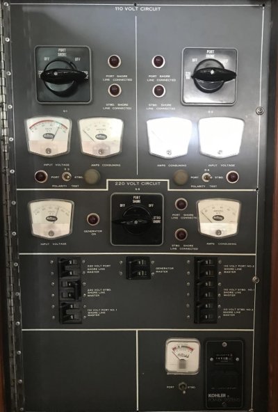
Thanks for the come back...... I like both plans, although I have to think how to do the GFI outlet with my 220V setup. (One leg at a time?) To give you an idea what I'm up against... here is the "Retro Encabulator" (AC electrical source selector panel)
 

Attachments

  • AC Source Panel.jpg
    AC Source Panel.jpg
    102.1 KB · Views: 15
Last edited:
@gkesden #3 needs a caveat; a standard clamp meter (Fluke 330 series, for example) does not have the sensitivity required to measure in the mA AC range. In fact, much below 3 or 4A AC is wishful thinking. A mA AC capable meter (Yokogawa) is about a $350 investment. Find a marine electrician with the meter and break out adapter and have him/her check your boat. A basic test won't take more than an hour.

@Comdave #3: I have personally tested dozens of boats using a breakout adapter and my Yokogawa. I rarely find a boat that is not leaking about 6mA AC. So, although your concept is spot on, it just won't work in my area as I have read about 100mA AC on a brand-new boat and as much as 15A AC on an older boat.

Marine Surveyors of North Georgia have made a test device that mimics what Comdave is discussing...it is pricey but could be a group buy at a marina or yacht club: https://tinyurl.com/95ztb8cf

Jim Healy is a really bright trawler owner and has written extensively about electrical issues on his blog. Here is a link to his article on the issue of AC leaks into the water column and how to test for and how to mitigate them. https://tinyurl.com/dnkep6ym

Since a significant part of my business has evolved into sorting these issues out, and in light of the number of marinas in my area that have upgraded their pedestals to include the 30mA/100mS RCDs, I have been faced with trying to troubleshoot the electrical system on a boat but can't get power to it because...the RCD trips! To better serve my clients, I am building a work around that includes a 600W inverter, a standard 30A twist lock shore power outlet and a Group 24 battery. This will only work on 30A shore power service but, it is a start.
 
@CharlieJ
The set ups I have seen for testing include an isolation transformer that plugs into the pedestal and keeps it powered. The boat then gets p,urged into the xfmr via adapters with separate conductors to use a clamp on ammeter. The setup can be mounted on a small cart por portability.
 
Can't you just measure the resistance between ground and neutral conductors? Start at end of the unplugged shore power cable and work towards the boat's branch circuits.

This should identify any neutral/ground connections on the boat. Disable the inverter as it will connect neutral to ground when not connected to shore power.
 
Last edited:
Jim Healy is a really bright trawler owner and has written extensively about electrical issues on his blog. Here is a link to his article on the issue of AC leaks into the water column and how to test for and how to mitigate them. https://tinyurl.com/dnkep6ym

Great article, thanks for the link.
 
...I rarely find a boat that is not leaking about 6mA AC. So, although your concept is spot on, it just won't work in my area as I have read about 100mA AC on a brand-new boat and as much as 15A AC on an older boat.

...

If the reverse polarity lamp is incandescent, you will have some N to G current thru that bulb. But, not enough to light it up. There will also be some N to G current through "Y" capacitors inside battery chargers, and the like. Used for EMC control. Doesn't explain the .1 to 15Amps tho! :confused:
 
I use one of these. It does AC and DC current to 1mA:

https://www.tequipment.net/Extech380950.asp

A friend uses one of these, which does the same:

https://www.tequipment.net/BK316.html

I think their resolution is 1mA and accuracy band is probably 2-2.5% vs ~1.5% for the similar high res models from top shelf brands (That cost $300-$600). The price of good equipment has come down a ton over the last several years.

In any case, these two seem to be plenty accurate for this purpose, and do clamp DC current, too, which is nice on a boat

BK Precision is obviously a venerable brand. I've personally had good luck with the Extechs so I saved the ~$40.

I think the Extech is ~$100 and BK is ~$140, each with free shipping. The BK is ~$20 cheaper with the education price.
 
Back
Top Bottom