Diagnosing a 6 tab rocker switch

The friendliest place on the web for anyone who enjoys boating.
If you have answers, please help by responding to the unanswered posts.

Dougcole

Guru
Joined
Jan 21, 2008
Messages
2,167
Location
USA
Vessel Name
Morgan
Vessel Make
'05 Mainship 40T
It appears that both of the Momentary/Off/Momentary switches on my Lenco trim tabs have failed at the same time, which seems very odd to me. I've ordered replacements, but I'd like to verify that the switches are indeed bad.


I've attached the wiring diagram for the switches. I'm getting 12.6 volts on my multi meter at tabs 2 (+) and 5 (-) but no voltage at any of the other tabs, even with the switch activated. I've also checked continuity across tabs 1&4 and 3&6 with the switch activated...nothing.


It feels like a bad switch to me, but why would both fail at the same time? Both were working on Friday, they failed on Sunday, so it's not like they sat for an extended period.


I was doing some other wiring (installed a USB outlet) on Sunday when I noticed they weren't working which made me think I knocked lose a wire, but like I said, I have voltage coming to the switches.


Ideas? Maybe I'm testing the switch wrong?
 

Attachments

  • Electric motor REV POL.pdf
    690 KB · Views: 57
You should never see continuity between tabs 1&4 and 3&6. The continuity would be from 1 to 2 and 4 to 5 with the switch down and working properly, and 2 to 3 and 5 to 6 with the switch up and working properly.
 
OK, I've got continuity between 1&2, 2&3 and 4&5 with the switch down. 5&6 with the switch up.


Seems like maybe it is working? That's not great news, actually, as it means it is something else. Maybe two bad actuators?


If I've got 12.6 volts at 2&3 shouldn't it be working?


I know I can test the actuators by running a jumper from them directly to the battery, but I haven't tried that yet.
 
What is the fuse or cct. brkr. rating for the tabs?
 
What is the fuse or cct. brkr. rating for the tabs?


I'm not sure what the rating is. They are fused with a 15 amp fuse, it's the fuse they came with when they were new in 2002, lol. The fuse is not burned out.
 
Put the switch in the up position and check for voltage with your black lead on 6 and your red lead on 3. If you see 12.6 volts, the switch is good in the up position and the problem lies elsewhere if the tab does not move.


Put the switch in the down position and check for voltage with your black lead on 4 and your red lead on 1. If you see 12.6 volts, the switch is good in the down position and the problem lies elsewhere if the tab does not move.
 

Attachments

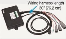
  • Lenco box.jpg
    Lenco box.jpg
    8 KB · Views: 24
Thanks for your replies. My version (older) of lencos does not have the control box. I'm going to go ahead and directly test the actuators. I'll update.
 
I suspect the voltage source to the switches. You may have enough to give you voltage with no load but goes away with load. Look for the green monster inside crimp lugs and the fuse holder.
Don't forget to check the negative leads as well.
 
I suspect the voltage source to the switches. You may have enough to give you voltage with no load but goes away with load. Look for the green monster inside crimp lugs and the fuse holder.
Don't forget to check the negative leads as well.


I was thinking the same thing, hence my recommended test measuring voltage (not continuity) with the switches activated. I'm guessing the voltage will drop substantially when the contacts both close.
 
Put the switch in the down position and check for voltage with your black lead on 4 and your red lead on 1. If you see 12.6 volts, the switch is good in the down position and the problem lies elsewhere if the tab does not move.[/QUOTE]


With black on 4 and red on 1 I'm getting zero reading with the switch in either position on the port side switch.


The ground and + wires jump from the port switch to the stb switch. On the stb switch I'm getting 12.6 volts at 2 & 5, same as on the port side switch. But 4 & 1 on the stb side with the switch activated I'm getting 0.9 volts.
 
I was thinking the same thing, hence my recommended test measuring voltage (not continuity) with the switches activated. I'm guessing the voltage will drop substantially when the contacts both close.


This is on my flats boat. I've never been real pleased with how it is wired, in that it doesn't have a negative buss or a central fuse panel. Rather there are breakers on the switch panel with jumpers going from one to the next. This is OK for the positive side of the switches, but anything that has been added to the boat, like electronics or the trim tabs relies on jumpers for the grounds, so the ground for the trim tabs is spliced into the ground for the bilge pump. It leaves a lot of room for a bad ground, in my opinion. I'm considering installing a blue seas fuse panel with a negative buss and wiring it directly to the battery. Do you think this is a good plan? I think that way I'd get a cleaner ground.
 
With black on 4 and red on 1 I'm getting zero reading with the switch in either position on the port side switch.


The ground and + wires jump from the port switch to the stb switch. On the stb switch I'm getting 12.6 volts at 2 & 5, same as on the port side switch. But 4 & 1 on the stb side with the switch activated I'm getting 0.9 volts.


That's really good news. You more than likely just have a bad connection upstream of the switches. Could be either the positive or negative lead. My money is on the fuse being corroded or internally faulty. Replace it and inspect/address the fuse holder for corrosion before you bother to trace anything else out.
 
This is on my flats boat. I've never been real pleased with how it is wired, in that it doesn't have a negative buss or a central fuse panel. Rather there are breakers on the switch panel with jumpers going from one to the next. This is OK for the positive side of the switches, but anything that has been added to the boat, like electronics or the trim tabs relies on jumpers for the grounds, so the ground for the trim tabs is spliced into the ground for the bilge pump. It leaves a lot of room for a bad ground, in my opinion. I'm considering installing a blue seas fuse panel with a negative buss and wiring it directly to the battery. Do you think this is a good plan? I think that way I'd get a cleaner ground.


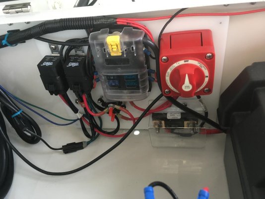
I think the Blue Seas panel plan is smart. Add a battery switch and a big main fuse while you are at it too. Coincidentally, I did just that last week while I was rigging my new dinghy. Don't forget the ugly but smart drip loops.
 

Attachments

  • IMG_2209.jpg
    IMG_2209.jpg
    99.3 KB · Views: 22
I think the Blue Seas panel plan is smart. Add a battery switch and a big main fuse while you are at it too. Coincidentally, I did just that last week while I was rigging my new dinghy. Don't forget the ugly but smart drip loops.


That looks great and similar to what I am planning. I like the way you mounted it all on a starboard panel, I'm going to do that too. I've already got a battery switch right next to the battery, so no need to add that.


With the shutdown, all of the marine stores here are out of yellow heat shrink ring terminals...grrrrr.


What do you mean by drip loops?
 
Order the terminals needed on line. I like supporting my local chandlery but sometimes I need to do otherwise. Will they not bring them in for you?


Drip loops are intended to get water to drop off a wire at a low point. If you run a wire from overhead of a fuse pane, CB panel or a buss the water will follow the wire right to the connection causing corrosion if there is not a drip loop.. The drip goes below the fuse panel, CB panel or buss and then back up a couple inches so the water will drop off.
 
That looks great and similar to what I am planning. I like the way you mounted it all on a starboard panel, I'm going to do that too. I've already got a battery switch right next to the battery, so no need to add that.


With the shutdown, all of the marine stores here are out of yellow heat shrink ring terminals...grrrrr.


What do you mean by drip loops?


Thanks, The seat base that panel is installed in is aluminum so starboard was a must. I don't think it would be good practice to build something like than on a conductor...


"Drip loops" just means that the low point of any wire is lower than the point where the wire terminates. This keeps drips from running down a wire into a crimp connector and beyond. They don't loom
kvery neat, but they are a good practice. Note how all my wires (I hope) droop.


I have since added some Dri-Dek to the bottom of the seat base and secured the connector in the lower left up higher.
 
Last edited:
Fixed.


You guys were correct, it was a bad ground. After wiring in the new fuse panel/negative buss and replacing some terminals on the switches they both work great. Getting 12.6 volts at the switches really threw me and sent me down the wrong path. I thought the grounds were OK. Whenever I do an electrical project my wife (who often messes up common phrases) tells me I'm no Einstein. I think she means to say I'm no Edison, but I'm never quite sure.


I've been meaning to do this for the flats boat for years, it's a 2002 that I've owned since it was new, so it's been bugging me for 18 years. Not enough to change it out though, I guess. LOL.


I just used nylon ring terminals for now, so I could get the boat running. I have a West Marine commercial account, I'll get the heat shrink terminals from them when they get them back in stock and then change them out. No big deal.


Thanks for all your help, truly very much appreciated.


Doug
 
Whenever I do an electrical project my wife (who often messes up common phrases) tells me I'm no Einstein. I think she means to say I'm no Edison, but I'm never quite sure.


You just tell her, "It's challenging, but it ain't rocket surgery"
 
You just tell her, "It's challenging, but it ain't rocket surgery"


LOL. Our older son is studying Software Engineering at Embry-Riddle, which is an aerospace university (quite literally rocket science). I'm going to start calling him a rocket surgeon.
 
Back
Top Bottom