Cat 3208TA alternator wiring to external regulator

The friendliest place on the web for anyone who enjoys boating.
If you have answers, please help by responding to the unanswered posts.

Pau Hana

Guru
Commercial Member
Joined
Aug 29, 2012
Messages
2,680
Location
Good Ol' US of A!
Vessel Name
Pau Hana
Vessel Make
1989 PT52 Overseas Yachtfisher
Hola!

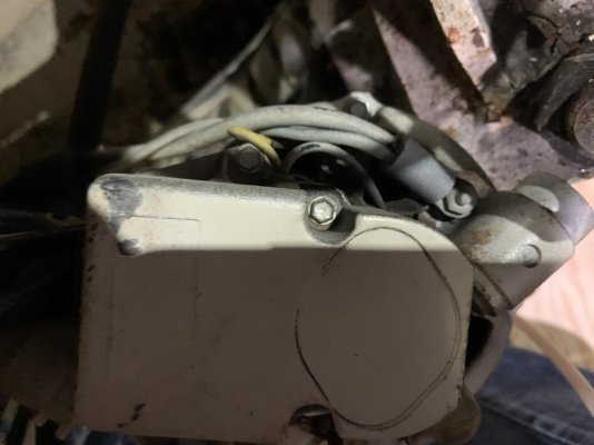
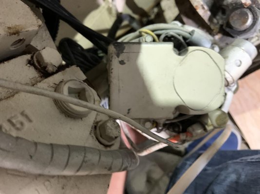
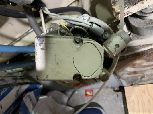
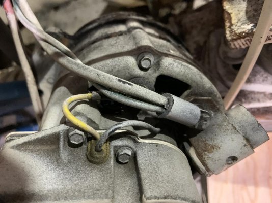
Prepping to install new Wakespeed 500 external regulators, and i'm looking to see if anyone has a wiring schematic for the 01Z 3208TA.

Specifically:

  • ignition wire (connected to switched voltage- zero volts when off and min 8.5vdc to activate)
  • Lamp wire- ground for charging lamp.


Thanks!
 
Standard 3208 alternator is integral regulated. Have you got externally regulated alternators? If yes then the standard automotive regulators should be there with 4 pin connectors. One terminal is spaced away from the others, that's Ignition, then Battery, Stator, and Field. The externally regulated alternators are positive-field. Charge warning lamp is typically connected to a specific terminal for that on an internally regulated unit, these are negative-field. Check your new regulator manual for charge lamp provision.

So, got to see the alternators you have or plan to use.

The alts are new Lee-Niceville externally regulated alternators, replacing the 51 amp Motorola alternators currently installed.

If you have a diagram, I'd appreciate it! Thanks!
 
110668640.jpg
Does the existing alternator look like this? (regardless brand) This is an integrally regulated, self-excited unit that does not use an ignition wire. If this is the case, and the engine has an activate-to-stop fuel solenoid, there may not be an ignition wire in the harness at all. If it has an energized to run solenoid you can simply take your ignition connection from the run solenoid. A good option for any case is to install an oil pressure switch for this purpose. The regulator assembly on these can be interchanged with an externally regulated version, it has two stud connections, possibly a one stud version too. The published engine wiring diagram, which goes by the engine arrangement number, might or not be what was actually installed, or what is there now. Provision for a charge warning light has to be in the alternator. If you have it you'll be giving it up with the new units, I think. So ignition is all you're looking for, take it off the solenoids or install oil pressure switches.

Have you tried fitting one of the new ones? The limited clearance to the exhaust manifold is an issue for upsizing. To install a large frame unit, I made a trunion mount which dropped the mounting down an inch or so. And my belt arrangement won't let me get a double on it, and it was an issue so I had a slightly larger pulley made.

Hope that's at least slightly helpful!
 
View attachment 112576
Does the existing alternator look like this? (regardless brand) This is an integrally regulated, self-excited unit that does not use an ignition wire. If this is the case, and the engine has an activate-to-stop fuel solenoid, there may not be an ignition wire in the harness at all. If it has an energized to run solenoid you can simply take your ignition connection from the run solenoid. A good option for any case is to install an oil pressure switch for this purpose. The regulator assembly on these can be interchanged with an externally regulated version, it has two stud connections, possibly a one stud version too. The published engine wiring diagram, which goes by the engine arrangement number, might or not be what was actually installed, or what is there now. Provision for a charge warning light has to be in the alternator. If you have it you'll be giving it up with the new units, I think. So ignition is all you're looking for, take it off the solenoids or install oil pressure switches.

Have you tried fitting one of the new ones? The limited clearance to the exhaust manifold is an issue for upsizing. To install a large frame unit, I made a trunion mount which dropped the mounting down an inch or so. And my belt arrangement won't let me get a double on it, and it was an issue so I had a slightly larger pulley made.

Hope that's at least slightly helpful!

That’s the alternator, but changed to external regulation.
 

Attachments

  • 0FCA754C-8354-4B01-9F5E-6AE0A2A38642.jpg
    0FCA754C-8354-4B01-9F5E-6AE0A2A38642.jpg
    60 KB · Views: 31
Last edited:
That is the currently installed unit, yes? (looks new, like it might be the upgrade)
OK, so then there are regulators nearby, similar to this one?:
PICT0402.JPG
If different, post a pic to ID it. The terminals on this style are, left to right:
Ignition+, Battery +, Stator, Field, Battery (-) to the case
 
That is the currently installed unit, yes? (looks new, like it might be the upgrade)
OK, so then there are regulators nearby, similar to this one?:
View attachment 112593
If different, post a pic to ID it. The terminals on this style are, left to right:
Ignition+, Battery +, Stator, Field, Battery (-) to the case

No, sir- currently the factory Motorolas (internally regulated) are installed, and are being replaced with the externally regulated Lee-Niceville units.
 
OK. We're looking for the existing harness wires to be used with your new regulator. Is the currently installed alternator like the one I posted, with a yellow wire coming out each side of the regulator assembly? If so, it is a self-turn-on and does not have Ign going to it. You will in that case use the run solenoid connection or an oil pressure switch. You mentioned charge warning light, do you have that and it works? If yes, and the alt is self turn on then the lamp will be the only small wire going to it. How many, if any, small wires are connected? Going with the self turn on assumption, do you stop the engine just by turning the key off? If yes then you have a run solenoid and can use that connection to turn your regulator on. You will probably find that wire goes to a relay closer to where you'll mount the regulator and you can connect there.
 
Following this... LOVE to hear what you think about the Wakespeed devices after you install them. They really seem like the next iteration in external regulators (next-gen)... :)
 
OK. We're looking for the existing harness wires to be used with your new regulator. (1) Is the currently installed alternator like the one I posted, with a yellow wire coming out each side of the regulator assembly? If so, it is a self-turn-on and does not have Ign going to it. You will in that case use the run solenoid connection or an oil pressure switch. (2) You mentioned charge warning light, do you have that and it works? If yes, and the alt is self turn on then the lamp will be the only small wire going to it. (3) How many, if any, small wires are connected? (4) Going with the self turn on assumption, do you stop the engine just by turning the key off? If yes then you have a run solenoid and can use that connection to turn your regulator on. You will probably find that wire goes to a relay closer to where you'll mount the regulator and you can connect there.

Appreciate the assistance!

Answers-
  • 1- The current installed alternator is the factory installed unit- I'll have photos of the wiring shortly.
  • 2 - The charge indication light come on after the engine is started and the engine RPM is increased
    to approximately 800 RPM.
  • 3- Will have photos later.
  • 4- The engine is stopped by a push button, which activates the stop solenoid.
 
Following this... LOVE to hear what you think about the Wakespeed devices after you install them. They really seem like the next iteration in external regulators (next-gen)... :)

Thus far- the interaction with Rick at Wakespeed has been excellent- much more so than with the Balmar folks...
 
Pau Hana,


What alternators are you using? I'm considering a similar upgrade on twin 3208 NAs. I plan on using Compass Marine's CMI-104-ER alts and Wakepeeds WS 500.


Both alts will serve the house bank which also serves as start bank. A single 8D sits in reserve for starting and will be kept charge up by a DC to DC chsarger. Undecided yet.

Exactly the alternators I have (externally regulated), purchased from Ballard Electric. I set up the new electrical so the alternators feed the house bank directly via the Victron Lynx DC distribution system. The start bank is isolated, and fed via a DC-DC charger.

I interviewed both Balmar and Wakespeed tech support folks, and found Rick T Wakespeed is highly knowledgeable of his product, and the tech aspects of the install are much simpler than Balmar’s. Instead of a spiderweb of wires from 2 Balmar 612s and a Centerfielder, a Wakespeed regulator (1 per engine) is programmed via USB, then connected via a simple ethernet cable.
 
So, with a push to stop there is no Ign feed on the engine. It might possibly still be in the harness coming from the helm and you could look for that if Cat panel & harness was used. But I would use oil pressure switches, though they are about $70 each. Stewart Warner/Hobbs p/n 76575 or 76576.

Lamp on to indicate charging is new to me, typical is lamp on indicates fault.
 
IF a rotary switch is use to disconnect the battery from an operating alt , the diodes in the alt can fry.

When upgrading be sure any rotary or other switch has field disconnect terminals on the back, and are part of the circuit.

I have seen rotary switches that had the field disconnects , that were never used.

Most alt fields are under 10amps , so the wire is not that expensive.

I’m installing Sterling APDs to protect the alternator.
 
Current alternator photos with wiring:
 

Attachments

  • 5D477D2A-D050-4131-BD37-0A9EF5523D69.jpg
    5D477D2A-D050-4131-BD37-0A9EF5523D69.jpg
    107.8 KB · Views: 22
  • 3286BA6F-77ED-40E8-8138-45E58DDD4208.jpg
    3286BA6F-77ED-40E8-8138-45E58DDD4208.jpg
    84.5 KB · Views: 24
  • A6FE1AF1-09FC-4FB6-A663-0BA9BAB92230.jpg
    A6FE1AF1-09FC-4FB6-A663-0BA9BAB92230.jpg
    97.2 KB · Views: 24
  • 650DE546-E9B0-49E4-A682-CAEDAAF7B880.jpg
    650DE546-E9B0-49E4-A682-CAEDAAF7B880.jpg
    119.7 KB · Views: 24
  • 35680FFA-A266-45CC-B97B-E6069C611E27.jpg
    35680FFA-A266-45CC-B97B-E6069C611E27.jpg
    145.4 KB · Views: 25
  • 21562F5B-E42E-4FAA-8164-1C819E80FD2A.jpg
    21562F5B-E42E-4FAA-8164-1C819E80FD2A.jpg
    95.7 KB · Views: 22
Self turn-on, no ignition wire. Look for it in the harness at the helm: Back of panel, wire from keyswitch to all the gauge + terminals - does it go into the harness? If yes, look for that color at the engine connector, verify with a test light. If no, options are run wires or install oil pressure switches. Ports for switches are convenient, on the cylinder heads, at rear on the alternator side.
 
EngNate,

Interested in your reunion mount that you fabricated. Can you share a picture?
 
I'll see what I can do for a pic on the engine. The attached crude drawing lays it out. I used 1/4" steel. I built-to-fit so I don't have any dimensions. It's two trunions (a U-shaped mount) back to back, so one attaches to the mounting ear on the engine and the other to the alternator, extending the alternator 1" or so out, down and outboard, from the original position, allowing the mounting of a Leece Neville 7000 series. I made the two trunions, mounted them respectively and held the assembly in place and marked for approximate belt alignment. Pulley shims were used for the final alignment - install some shims before the first step.

It's very important that the pieces of this assembly are cut precisely at joins, drilled in perfect alignment, and assembled pretty precisely square and parallel to avoid angular misalignment. Nonetheless I made mine with basic shop tools. I spaced mounting ears by assembling with a piece of paper grocery bag between and tacking in place.

Make one trunion a bit wider than the other for the bead when they're welded together, and position ears so they get a bead on both sides.

The belt arrangement I've got isn't the ideal solution but it works OK, such that at 6 years since, improving it hasn't yet made the priority list although it's on the wish list, mainly because I'd like to restore the dual belts on the jacket water pump. I'll post some pics and more details next day or so.

View attachment AltBrkt.pdf
 
Exactly the alternators I have (externally regulated), purchased from Ballard Electric.

The ER kits for these alternators were discontinued back in 2017. Last I knew Ballard was out? Ballard has a pretty good pile of used stuff so perhaps they found a few kits in the scrap bins?

We re-imported slightly over 200 of these kits from a major distributor in Europe $$$ and then, after many months of begging and pleading with LN, were able to get Leece-Neville to do one last large production run for us. We are nearing the end of these and have had zero luck getting anyone to make these for us that won't cost over $100.00 per kit.

Good to know- appreciate the info (and the pic from your site!)
 
Further details on the mounting bracket... It offsets the location by 2-3/4", not an inch or so. I'd make that 2-1/4", as the clearance at the bottom is tight. Pardon the rust, haven't cleaned it up after the raw water pump seal went. And I didn't make it neat, it was to be a prototype and improved on later, you know how that goes.

This was necessary to get enough pivot range for belt adjustment.
The bolt center spacing below is 2-3/4", but ought to be a little less.
20210119_142243.jpg
20210119_142408.jpg
20210119_142320.jpg
Note the position of the adjusting arm point on the alternator, about 120 deg or so from the pivot. Further towards 180* will conflict with the cross-member. Pulley OD is 4". The standard pulley (2-1/2 - 2-3/4) definitely wouldn't do it, I guessed how much bigger to go and the 4" is more than good. Mine is the 85 Amp version of this heavy duty series which goes to 160A. A smaller, lighter alternator would get one more output for the belt load, but this is really about the max you can drive with one A belt. So one belt wraps the jacket and raw water pumps and one the alternator only.
 
Last edited:
This attachment failed. I had to cut the bracket as shown below:
20210119_142150.jpg
I also made a small tapped plate in place of a nut on the adjusting arm, as a wrench can't get behind there.
 
Last edited:
I found easiest is to install an oil pressure switch and then run fused positive lead from starter to switch. Run wire from pressure switch to alternator. No oil pressure no power. Beats trying to chase down the lead from the electrical panel. I can tell you where the 1/8 pipe outlet is for the switch if you pm me.
 
Mastervolt Aplha Pro lll

I just wanted to post on this thread as I have just carried out this job on a pair of 3208’s.

We had just installed a victron Quattro along with 3x 200ah lithium batteries and the kit to go along with. We decided to go down the alpha pro rout for regulating the alternators.

When we had the alternators on the bench we pulled off the existing regulator (4 small machine screws) and cut off any of the existing wiring to the old regulator and disconnected the spade connectors from the brushes (magnetic field connections). It’s important to check each brush is isolated from any other part of the alternator. You should have continuity between the two brushes. You want to keep the old regulator as a cover. It has nice little rubber grommets you can use to rout your new field wires out from, keeping the brushes nicely sealed when reinstalled after the modification. On the alpha pro there is a blue field wire that needs to be connected to one of the brushes and a red positive wire that needs to be connected to the other brush. Polarity is not sensitive here. This connection now allows the alpha pro to pulse the magnetic field on and off as required to control the out put of the alternator. We made nice little jumper leads to come connect to the brushes on spade connectors heat shrinked them all and ran them out through the grommets on the old regulator allowing us to easily connect to the alpha pro.

We installed an independent lamp for each on the dash for the yellow lamp circuit (charge lamp/warning indicator) and ran the brown on/off wire from an ignition live which was easily found at the helm station panel.

The system is now fully installed and is working like a charm.

Will try and up load pictures soon.

Callum
 
The goal of an external regulator is it can be chosen to charge the battery bank faster and better than a regulator built just to recharge a car or truck.

The 3 or 4 stage regulator built for recharging a boat house bank is the goal.

Many older large car 60's & 70's Caddys had external regulators , that can be swopped out for the marine style units. Sadly if used hard with out a temperature monitoring circuit they are rather short lived.

Large frame truck alts do not have this problem , only the hassle of fitting to the engine.
 
So my CAT 3208T/A are rated at 52amps. So 104 amps total. Not enough?
 
So my CAT 3208T/A are rated at 52amps. So 104 amps total. Not enough?

Tom, they were 52a when new, and that was the max output at speed.

Lee-Niceville makes a bolt-in 110a alternator that can be easily converted to external regulation.
 
Back
Top Bottom