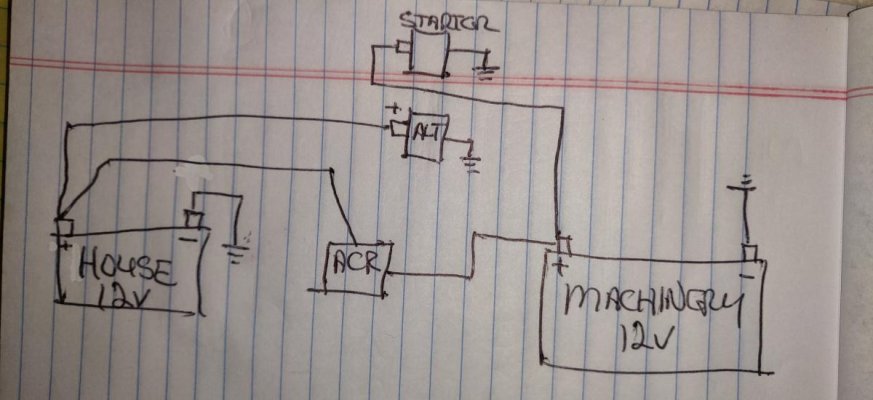
All the posts were interesting, but I think I'm commenting primarily on the post from FlyWright. I tried to add a figure, but it didn't work. In my single-engine system, the as-modified system The start battery(bat2) connects directly to the engine starter, engine panel, thruster and windlass. It also connects to the manual selector switch and the combiner. The alternator is connected directly to the starter and there to the start battery. There is a previously-installed inverter/charger that connects directly to the house battery(bat1). The house battery is also connected to the combiner and manual selector switch. There are various fuses in the system, but the alternator output is not fused. If it fails in a short mode I expect the internal wires will burn open or the external wire, which is short and not near other wires, will melt open. It is a fairly simple system and seems to work in any known mode without fault.
")