@Frosty
The ABYC Standards (and ISO Standards and the NEC for that matter) establish "rules". With these "rules" come exceptions with the most conservative approach being to build to the "rules" and only use the exceptions when absolutely needed. But your comments, so far, certainly imply that you understand this.
So you are saying that even if the batteries are fused individually, one still needs the same fuse for the group that you would have if you didn't fuse them individually? I guess I had better brush up (or maybe I never understood it correctly).
Short answer is "yes". Here is my logic.
The AIC rating of a fuse is based on:
1) The fusible element must melt as required by its designed time/current curve.
2) When the fusible element melts, the arc that is created must extinguish as it is a conductive plasma.
3) The fuse can not physically blow apart.
So for the AIC to really come into play, the protected circuit must experience a bolted fault. This is generally a very, very, very rare occurrence.
From a circuit design POV, for DC systems, voltage drop is generally the constraining variable that we have to design to. Conductor ampacity generally follows. In other words, if the voltage drop is accounted for the conductor ampacity will usually be sufficient.
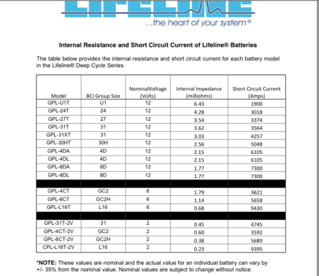
For a real world design, your three Lifeline AGMs have a short circuit current of 4257A. The design should account for the voltage drop between the three batteries and the B+ and B- collecting bus bars.
An example design:
Battery whips. For this example the B+/B- circuit length from each battery to the bus bars is 6 feet. Most DC panelboards have a 100A or 50A main breaker. Assume 100A. So each battery will have to produce 100A/3 = 33 A for the DC panelboard. I would probably spec AWG 2/0 for the battery whips. Engine room ampacity is 280A and the 6 foot circuit to feed the bus bars would yield an IR drop of <<3%.
Panelboard Feed. AWG 1/0 will provide an IR drop of 3% to 30' of circuit length. AWG 2/0 will provide an IR drop of 3% to 44' of circuit length. For the example I will use 2/0 with an engine room ampacity of 281A.
Inverter/Charger. A 3kW inverter/charger is fed from the same collecting bus bars. A Victron Multi-plus calls for a 400A fuse and 100mm^2 conductors for up to 5m of circuit. 3000W/12.5VDC = 240A (assuming 100% efficiency). The example Multi is fed by 4/0 B+ and B- with an engine compartment ampacity of 378A.
Full Load. At full load the three batteries are going to have to provide 240A for the I/C and 100A for the DC panelboard for a total of 340A. Each battery must provide 340A/3 = 113A. The IR drop for the whips is still << 3%.
Whip OCPD. Finally, and I apologize for the length of this lecture, I would protect each battery B+ whip (250A MRBF to protect the AWG 2/0 whips (E/R ampacity = 280A) from the individual battery to the collecting buss.
Panelboard Feed OCPD. I would protect the DC panel board feed (AWG 2/0) with a 250A MRBF on the collecting bus. My rationale being that the total SSC of the three batteries, at 12.9VDC is 12.7kA. The AIC for the MRBF is 10kA at 14VDC. There is some headroom there as the nature of AIC is that it diminishes with rising voltage. If I was super conservative or designing for a USCG Sub-chapter T boat, I would spec a Class T fuse and fuseholder.
Inverter/charger feed. I would protect the B+ 4/0 feed (E/R ampacity 378A) to the I/C with a 400A Class T fuse and fuseholder. This last is permitted by the ABYC Standard as a Class T 378A fuse is not available. The Class T AIC is 20,000A @125VDC so there
is a lot of headroom with this fuse.
The above design is conservative, meets the spirit and the letter of the "rules" and I can sleep well at night after installing such a system. The exceptions to the ABYC "rules" are attached. Clearly, Exception #2 could be used to eliminate the battery whip MRBFs. It is
my opinion that the cost of the MRBFs is so low and the added protection is very worthwhile.
So the short answer is "no" if you want to use the exception that is clearly laid out in the "rules". I just choose not to.
 ), I've decided to stick with Lifelines for now. Why buy expensive new batteries and let them sit. But I imagine I will reconsider LFP in the future. Being able to calculate the potential short-circuit current myself will be a plus, so I appreciate the info.