2x30A shore to 50A on board?

The friendliest place on the web for anyone who enjoys boating.
If you have answers, please help by responding to the unanswered posts.
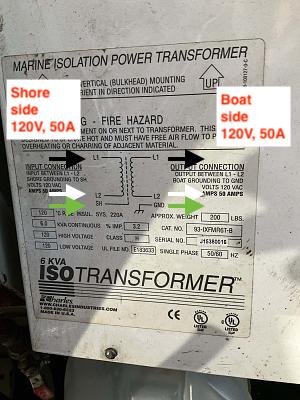
It looks like (from the label) your current Isolation Transformer's Input is limited to 120V, and single phase.

If so, it will not work with 240V split phase supply, nor will it produce 240V split phase.

Your quickest remedy remains a separate 120V 30A supply from the other pedestal that you keep entirely separate from the existing boat wiring. New inlet, breakers, wiring, buses, branch circuits breakers and branch circuits as usual. Use it at a current draw of no more than 24A if the load is for more than about a minute.

I read the transformer as L1 and L2. 120v each leg. Which would give you 240 for a 220 appliance.
 
Thanks. Pictures are worth a 1000 words, and how many posts on TF? :)


The shore pedestal was at your old slip, correct? It shows a single pole breaker, and a 50A 120V outlet. All that's consistent.


And your boat's inlet and shore cable are both 50A 120V.


You have mentioned that your new slip has 30A 120V outlets and that thee aren't any 50A 120V outlets. But I don't know if it was ever asked or said whether there are any 50A 120/240V outlets nearby? I have perhaps assumed there aren't, but should ask explicitly.


I take it back. That pedestal is 30A 120V. The pin configuration is the same, but the plug body is very different from the 50A version. Hard to tell the body size from the photos, but the breaker is clearly 30A.
 
I read the transformer as L1 and L2. 120v each leg. Which would give you 240 for a 220 appliance.


There is no neutral, so it's not split phase. So I think Luna is correct. A split phase 120/240V 50A transformer would be rated for at least 12KVA, and this one is rated for 6ka which is consistent with a single 50A 120V shore cord.


So any second line brought on board would need, in addition to everything else outlined already, it's own isolation transformer or galvanic isolator in accordance with ABYC. Or if the inlet were converted to 50A 120/240V, the iso transformer would need to be changed out for a 12ka split phase transformer, again in accordance with ABYC.
 
Adding an isolation transformer to the the 30a line would be potentially wasteful if you up graded. The isolation transformer wouldn't really be needed as this line would not tie into any of the boats grounding systems. Just don't ever add a battery charger to the second line. You will need to run ground wire specifically for the heaters. You would not want to tie into the existing ground wire system.


Are you saying that the second line connection will be totally isolated from the boat’s ground system, if it is wired independently from the source (shore), to cable/inlet, inlet to panel, panel to breakers, breakers to wire, wire to appliance?
 
The Label reads the Input is between L1 & L2. The shore grounding (the green wire) goes to the SH (shield). The Volts (are) 120VAC. That's all we know from the Label.

With 120V you (normally) only have 3 wires, one of those, (the green wire) goes to the shield. That leaves the Ungrounded (black) wire and the Grounded (white) wire, commonly called the Neutral wire to go on what Charles calls L1 and L2 respectively. The voltage between the Black & White wires as the label says is required, is 120VAC.

You've now run out of wires and terminals. What could possibly go wrong?

To confirm this you must review the manual for this transformer which can still be obtained (I just checked ) from the Charles Ind. website. Search the Cat. No.

There is a Neutral, in this case it's brought aboard and connected to L2. What isn't there is any center tap as it's a 120VAC transformer.
 
The Label reads the Input is between L1 & L2. The shore grounding (the green wire) goes to the SH (shield). The Volts (are) 120VAC. That's all we know from the Label.

With 120V you (normally) only have 3 wires, one of those, (the green wire) goes to the shield. That leaves the Ungrounded (black) wire and the Grounded (white) wire, commonly called the Neutral wire to go on what Charles calls L1 and L2 respectively. The voltage between the Black & White wires as the label says is required, is 120VAC.

You've now run out of wires and terminals. What could possibly go wrong?


I am not recommending wiring up a transformer from its label. I would want to see the manual before I did anything. Since the label is not completely readable for me there is no guarantee that I am not missing something

To confirm this you must review the manual for this transformer which can still be obtained (I just checked ) from the Charles Ind. website. Search the Cat. No.

There is a Neutral, in this case it's brought aboard and connected to L2. What isn't there is any center tap as it's a 120VAC transformer.


The Label tells me that I can connect L1 to L1 and L2 to L2. No N is used as L1 acts as neutral for L2 and L2 acts as neutral for L1. Ground is connected to shield. There are other ways to use the transformer and I am sure you will find these options in the manual.

So with L1 and L2 being used you get 240v

It’s Thanksgiving and I’m not describing things well at this point.
 
Last edited:
I think we all agree that without seeing the manual we are not 100% sure what can be done with the transformer.
 
Happy Thanksgiving!

Have a look at the manual tomorrow afternoon and let me know your findings.

In the meantime, enjoy the festivities!
 
Get a certified marine electrician to come and plan the system. Then you can build it if you feel comfortable with doing it. Too many cooks in the kitchen here.
 
The Label tells me that I can connect L1 to L1 and L2 to L2. No N is used as L1 acts as neutral for L2 and L2 acts as neutral for L1. Ground is connected to shield. There are other ways to use the transformer and I am sure you will find these options in the manual.

So with L1 and L2 being used you get 240v

It’s Thanksgiving and I’m not describing things well at this point.


If you wired it that way there would be three issues.


1) On both the primary and secondary sides you would have 240V across L1 & L2, and the transformer is only rated for 120V. You might get away with that, but it's outside the transformer's ratings so shouldn't be done.


2) On the secondary side you have 240V, but no center tap to create a neutral, so no way to get split phase without adding more equipment.


3) The transformer is rated for 6kva, so at 240V you are limited to 25A.


The intended wiring is shown in the marked up diagram below.
 

Attachments

  • IsoXfmjpg.jpg
    IsoXfmjpg.jpg
    29.7 KB · Views: 107
Too bad they marked the connection points L1 & L2. I expect that to be Line hot not neutral, yet did not make sense when the label is read 120V.
 
Too bad they marked the connection points L1 & L2. I expect that to be Line hot not neutral, yet did not make sense when the label is read 120V.


Line and Neutral are completely interchangeable on L1 and L2 on both primary and secondary, and I expect that's why they are labeled as they are.
 
IMG_0216.jpgIMG_0217.jpgIMG_0218.jpgIMG_0219.jpgIMG_0220.jpg

Few pages from the manual. I hope this helps.
 
How do you get 50 amps into that connection from the 30A pedestals.


Have you asked the marina, at your expense to redo a pedestal from 30 to 50?


1/ I don’t at this point. Second inlet, panel, wiring, is something I might consider. Another 30A isolation transformer, too.

2/ I did. It is a possibility in the future. There is no emergency. If I stay, I’ll pay.
 
Now that I see the manual its clear that this is a 50a 125v unit. I believe It is labeled L1 and L2 because you can add a second one if you have 50a 125/250. I can never remember these things off the top of my head so with out looking things up I believe you need to reverse the second one so that the neutral doesn't get over loaded.

My point is that Leoka should consider the possibility of using a 50a 125v isolation transformer on the 30a second line. This would give the ability to upgrade to 50a 125/250v. Not telling you this is what you should do but think this project through before you start. You do have several options.
 
If the 2 hots from the 2 pedestals are in phase (same line, measure 0 volts between them) you can use (2) 30 amp cords and parallel into one 50 amp socket to match the boat.

Yeah, I know this violates code, but if both cords are same gauge I don't worry about the clamps in the socket having contact problems.

Ain't going to be pretty either with this "Y" cable snake coming along both side of the boat, but it will work and since you have 2 parallel neutrals and grounds too there will be no overload.

Yes you will have a 60 amp shore breaker going into your 50 amp boat breaker, but I don't see any difference from a home setup where the street is going to deliver more than the main (house breaker) can handle.


Here's a repeat from post #57 about why you should never do this, even though it can provide power as you say.


Electrically you can do this, and it's what the bootleg ParkWorld adapter does. But doing so is potentially very dangerous. No offense intended, but you guys have demonstrated that you should not be messing with such stuff. What you are contemplating, which is paralleling two independent power circuits, violates every electric code, every building code, every boat wiring standard, and is just a horrific electric practice. I can think of only a small handful of people on this forum who know enough to safely do such a thing, but none of them would ever do it because it's so totally wrong. All it takes is someone inadvertently moving one of your plugs to another outlet to create a dead short. Or to unplug one end and touch a prong and get electrocuted. Or an electrician who turns off power to a pedestal to work on it, only to find that it's still live and he's now dead because you are backfeeding it through your adapters. DO NOT DO IT. I don't know how to be more emphatic about this. This is what kills people, burns down marinas, and does other socially unacceptable things.
 
At this point, I have no intention to mess with my existing 50A circuit. It is working fine, when I have 50A pedestal. Either with an adapter to convert the shore 50A/126/250V, or just strait 50A/125V, if that is the pedestal.

I will build up a new connection for 30A. It is very common everywhere, and will be perfectly enough to have it as an addition. 30A plug, cable, inlet, isotransformer, panel, a/c sub panel, appliances.
This is all I need. On the daily life, I manage fine with just one 30A connection. Even with a larger load appliance, if I am careful what to turn on. If I had a second 30A connection added, my electrical feed will be plenty enough and more comfortable.

So, there is no need to convert, or parallel anything. I certainly want to be on the safe side.
 
I have a similar electrical setup. I have an isolation transformer that only takes 50 amps and I quite often run into only 30 amp service. I use a Hubbell 230 YQ when I run into 30 amp service. It tests the circuits and gives you a greenlight when the 2 circuits are compatible, not in phase, and will power the boat. When there is no greenlight the dock circuits are not wired correctly.

It is a very simple device, that will protect your boat. Yowser, I just checked the current prices, it is spendy, the quick search I just finished had the lowest prices in the $800s.

I paid less a few years ago and it has been very helpful easily $800 helpful. I like the confirmation that the electrical supply is wired correctly.

MIke
 
At this point, I have no intention to mess with my existing 50A circuit. It is working fine, when I have 50A pedestal. Either with an adapter to convert the shore 50A/126/250V, or just strait 50A/125V, if that is the pedestal.

I will build up a new connection for 30A. It is very common everywhere, and will be perfectly enough to have it as an addition. 30A plug, cable, inlet, isotransformer, panel, a/c sub panel, appliances.
This is all I need. On the daily life, I manage fine with just one 30A connection. Even with a larger load appliance, if I am careful what to turn on. If I had a second 30A connection added, my electrical feed will be plenty enough and more comfortable.

So, there is no need to convert, or parallel anything. I certainly want to be on the safe side.


I think it's at least worth considering converting your inlet to 50A 120/240V rather than adding a separate 30A inlet. I don't know which would ultimately be better, but I think it's worth evaluating both. Tradeoffs as I see them are:


- Switching to 50A 120/240V involves swapping out the 50A 120V inlet. No new hole drilling, finding space, etc.


- Change existing 50A single pole breaker to a two pole, though you may already have a 2 pole for breaking L & N. In that case just rewire for L1 & L2.


- You double you available onboard power rather than about a 30% increase.


- You are planning new panels etc to add 30A 120V, and it shouldn't be any harder to change the existing panel to split phase.


- Swap out the existing 50A 120V iso transformer for a 120/240V iso. It's unlikely to take up more space. Adding 30A service requires finding space for a new iso, input and output breakers, etc.


- A good 50A 120/240 iso transformer can be wired with a switch to boost 208V shore power, if needed.


- A good 50A 120/240V iso can be wired for 30A 120V input, if desired. You won't get more than 3600W, but it's super convenient. I've never looked into it, but I expect it could be wired to accept 50A 120V as well. Note that either of these options will involve adding an appropriate inlet plus a selector switch to select which input to use.
 
I have a similar electrical setup. I have an isolation transformer that only takes 50 amps and I quite often run into only 30 amp service. I use a Hubbell 230 YQ when I run into 30 amp service. It tests the circuits and gives you a greenlight when the 2 circuits are compatible, not in phase, and will power the boat. When there is no greenlight the dock circuits are not wired correctly.

MIke


Protecting the boat is a priority, of course. If I look at the new circuit setup, it will not be cheap either, but it can be used anywhere later on. If I spend $800 on an adapter and my pedestals are not in sync, I’ll be safe with the adapter, but will not provide anything.
 
I think it's at least worth considering converting your inlet to 50A 120/240V rather than adding a separate 30A inlet. I don't know which would ultimately be better, but I think it's worth evaluating both. Tradeoffs as I see them are:


I am not sure, if it is economical to get rid of my existing transformer, just to spend another 2-3K for a new one. Yes, it could be the best option and I have no idea why the previous owner did not go that route, but it is there and working fine.
Adding a new circuit might not be the best setup, but a new 30A transformer is much less costly and smaller in size.
 
If possible change the pedestal plug, or add the 50amp circuit one if you plan to be in that spot for a year or more. At least do a cost comparison, onboard v. on dock cost
 
If possible change the pedestal plug, or add the 50amp circuit one if you plan to be in that spot for a year or more. At least do a cost comparison, onboard v. on dock cost


It is not just about the money. Obviously it would be cheaper just to pay the marina for the pedestal replacement. If I add a new circuit, it will cost me more. Adding another transformer, a new panel, source selector, etc. could be way over 1K. However, a new circuit could benefit the boat for the future, too.
I plan to stay in this marina for at least another two years. Family obligations require it. Unfortunately, the ownership is changing here, as the marina is being sold now. The rumor is, there will be changes, perhaps structural, to increase the capacity and other reasons. This will certainly require to move the boats around. I am not sure if I will be able to stay at the same slip, and/or the new structural change will include upgrades to 50A pedestals? No one knows anything for sure at this point. So, why should I pay for a new pedestal, if I end up in a different dock?
For these reasons, I’d like to figure out an economical solution for another circuit. Not urgent, as I am doing fine now. It is just something I believe is worth the investment for my boat’s sake.
 
I am a bit confused by this whole thread. I have a 30 amp connection and a 50 amp connection on my boat. The owners manual says two 30 amp connections, one for AC and one for everything else. The 50 amp is the only thing I have plugged in and everything works. I can find nothing on the boat that takes 240 volts yet I can check 240 volts between the two halves of the panel so, shore power is definitely 50 amp 240 volts. I do have an isolation transformer.
How is it that he only has a 50 amp 125v connection? What am I missing? can docks have both 240 and 125v or is his boat dropping one leg?
I am about to hook up a generator and was going to investigate all of this when I return to the boat.
 

Latest posts

Back
Top Bottom