Rudder shaft removal

The friendliest place on the web for anyone who enjoys boating.
If you have answers, please help by responding to the unanswered posts.

CharlieO.

Guru
Joined
Sep 21, 2020
Messages
1,547
Location
Lake Champlain Vermont, USA
Vessel Name
Luna C.
Vessel Make
1977 Marine Trader 34DC
This is one of those projects that requires moving a bunch of other stuff.

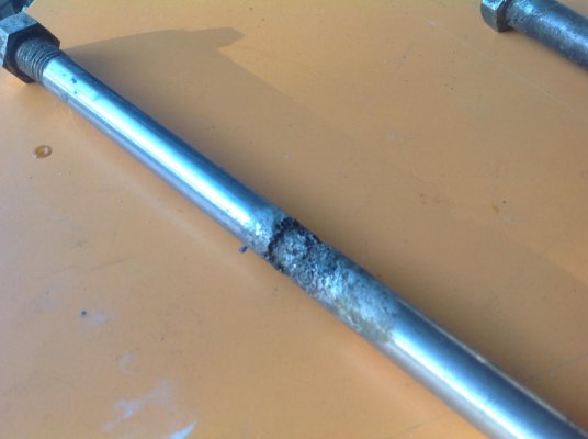
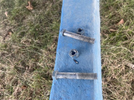
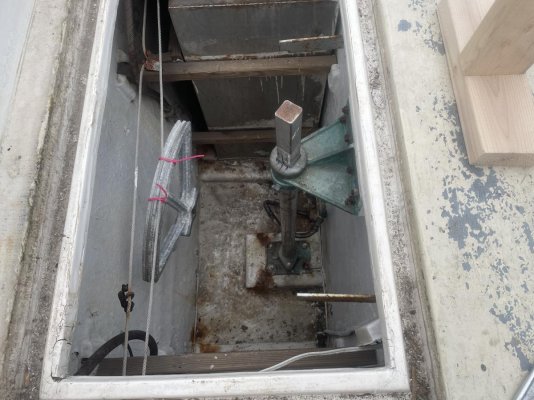
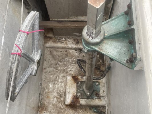
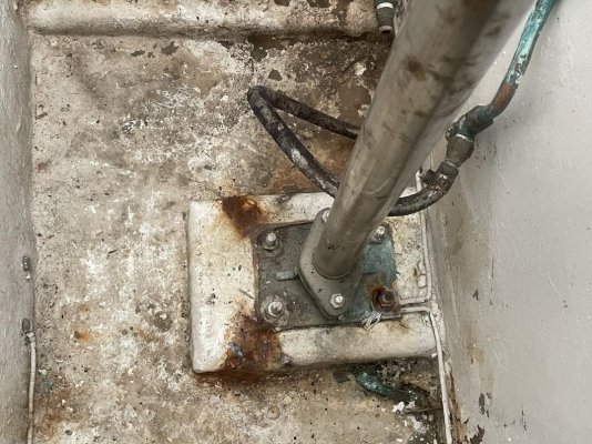
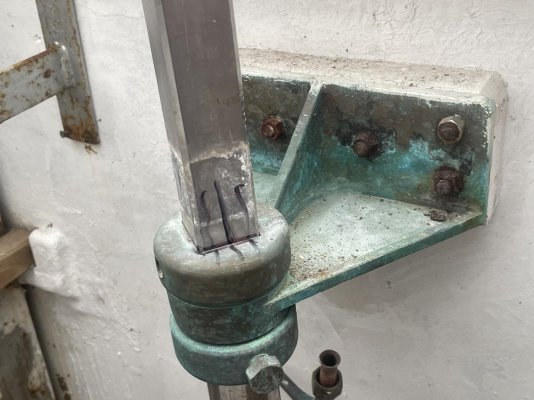
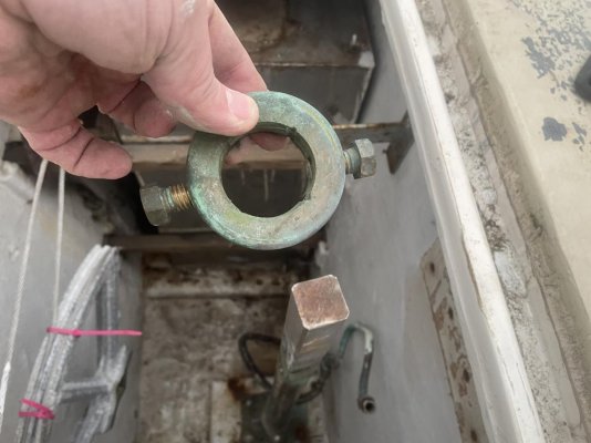
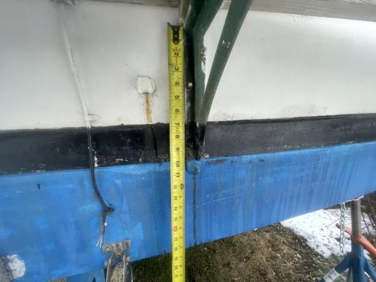
Project is to replace my swim platform brackets. I want to remove the old ones, check and likely add additional backing for said brackets in the laz. But I need to remove both water tanks, but to do that I need to remove the rudder shaft. Then I can get down there to do the work.

What should I know or take into consideration when doing this job.

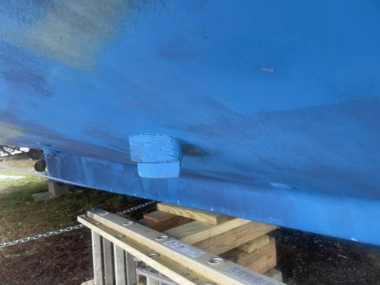
Also what about removing those transducers?
 

Attachments

  • 75DFC36D-E564-4A60-BD63-1FE254C7D7BF.jpg
    75DFC36D-E564-4A60-BD63-1FE254C7D7BF.jpg
    195.1 KB · Views: 58
  • 2611E92E-F0AD-4B14-83DE-D75F241A44A5.jpg
    2611E92E-F0AD-4B14-83DE-D75F241A44A5.jpg
    144.1 KB · Views: 38
  • ACA2ED3A-7A4E-469C-A0DC-9F14043E52CA.jpg
    ACA2ED3A-7A4E-469C-A0DC-9F14043E52CA.jpg
    179.5 KB · Views: 40
  • A95AFCBF-14C0-47F5-B10E-7313D8715481.jpg
    A95AFCBF-14C0-47F5-B10E-7313D8715481.jpg
    123.2 KB · Views: 39
  • 9C07A6CB-D96D-4C67-8339-B01DC47B1082.jpg
    9C07A6CB-D96D-4C67-8339-B01DC47B1082.jpg
    149.6 KB · Views: 32
  • 1D9CAA61-730F-4F86-AC61-A5F2D1162F85.jpg
    1D9CAA61-730F-4F86-AC61-A5F2D1162F85.jpg
    155.2 KB · Views: 43
  • B869DB74-0BA1-4EE8-8670-EF490D8269B0.jpg
    B869DB74-0BA1-4EE8-8670-EF490D8269B0.jpg
    92 KB · Views: 32
  • 40B252FD-3A48-48AE-8BAC-8ABACB79C468.jpg
    40B252FD-3A48-48AE-8BAC-8ABACB79C468.jpg
    119.8 KB · Views: 35
I cannot see where the transducer is a problem.
 
There is one on each side not hooked up to anything. The underwater portion of the block doesn't seem as solid as it should be.
Transducer or earth for a removed SSB radio?
 
Not hooked up to anything? Get rid of 'em.
 
I glassed 6 holes closed on our last boat. PO didn’t remove anything redundant. Be sure to use epoxy for strength and secondary bonding.
 
Queer steering arrangement using a quadrant, cables and turning sheaves but I guess with two FW tanks crammed in their you couldn’t properly run rod linkage but hydraulics may be cleverly installed especially a Wagner T-Head unit or one of their other solutions.

I can promise you as you tear into this project there will be no shortage of surprises. Looking at that rudderport installation where they cut out some glassed ply and the doubler or support blocking gives me pause. Plus those water tanks have the typical stainless steel burned welds that cause leakage from pin holes and worse. You’ll be lucking to remove them without breaking welds. Make sure they pressure test and roll them to see if the baffles are still intact. I wish you good luck though

Rick
 
Rick, could you expand on your thoughts on the "rudder port installation" are you referring to the base where the rudder shaft comes through the hull?

Thanks
 
It looks like the transducers will be the smallest part of the project. Might be a good change of scenery to work on them after working on the tanks and post.

pete
 
Well first off I can’t understand how or why the the rudderport plate is installed is that crammed space that was cut out. It appears the builder or somebody cut away the plywood shelf ? to the left in the third photo. There is a transom knee to starboard but none visible where that plywood was cut out. So the rudderport plate is a tight fit and it shouldn’t be. I have to wonder if the hull surface was faired off to mate with this plate then properly bedded or just set down on lots of compound. I notice bedding compound under the bolts and washers and the squeeze out pattern suggest it was applied then washers and nuts which wouldn’t be needed of the plate is properly bedded. I wonder what the compound is and if it’s 5200, which I doubt as early Taiwanese builders didn’t have it or use it. Anyway it would be a good idea to cut some of this stuff and see what you’re dealing with

One bolt and nut has been replaced, back right, which is a red flag since it means the rudderport was not removed but one bolt had a problem and whoever replaced it left the old bedding compound in place instead of new. The other plate bolts look like SS and therefore very suspect from crevice corrosion. So they should be drawn and closely inspected for pitting and replaced as necessary, ( see attached photo ) . The rudder stock (shaft) may also have a crevice corrosion issue where it resides in the rudderport tube and lacks sufficient oxygen to prevent this. I would also take a close look at the packing gland for wear or corrosion and replace the two bolts and nuts. In summary I think you need to do more that just unship the rudder but remove the entire rudderport assembly and I’m afraid you’re going to find some conditions that are going to require, grinding, fairing and probably glass work to create a decent amount or working clearance. If that plate is not just bedded but is bonded with something like 5200 then you’ll have a heck of time getting it up.

The rudderstock carrier in the second photo is bolted to a mounting block that is attached to the inner transom skin somehow but are the four bolts just attached to this block and if so how is it done. One last thing, the rudderstock appears to be pinned to the rudder so it would be smart to drive them out for inspection. About all I can tell from the photos.

The bolt in the photo is a prime example of advanced crevice corrosion discovered with my ultrasonic equipment. You also might noticed the fracture under the bolt head upper right corner.

Rick
 

Attachments

  • BF24A874-6C87-4D09-8651-A67BB90F2673.jpg
    BF24A874-6C87-4D09-8651-A67BB90F2673.jpg
    64 KB · Views: 21
Last edited:
Rick, thanks for your time looking at the pics and comments. I'll definitely take a closer look at everything next trip up to the boat.

My pictures may be a bit misleading or I might lack a bit of understanding. The rudderport plate on the bottom isn't recessed into the block but is mounted on top. You can't quite see the left side of the picture but it looks the same as the other side. The upper rudderstock support is through bolted through that block and the bulkhead between the lazarette and the aft stateroom, not the transom.

I've never seen any water back there except a slight bit on top of the packing. Never seen it dripping or anything just water sitting on top.

Next time I'll take better pictures from inside the laz and may have more questions after I do a more in depth examination.

Thanks again, Charlie

Okay Charlie now I see it. I had the lazarette turned around so as you say the upper rudder stock carrier is bolted into the forward lazarette bulkhead and not the transom. So those tanks are kind of skinny huh ? So never mind my remarks on that. Sorry

Rick
 
Yeah Rick, I think those tanks are about a 1\2 inch smaller each way than the hole. I'm not opposed to changing the tanks if needed. We run out of holding tank faster than we run out of water, and I'm also always looking for anywhere I can add storage.

The steering is chain from upper helm to lower helm, chain from lower helm to shaft in engine room, from aft of engine room shaft is chain to another shaft alongside the starboard side of hull behind paneling in aft stateroom. I'm not sure what is used for the transition from the most aft end of the shaft in the lazerette and the cable. I'll find out once I take out the tanks. I am real happy with the steering, it's fairly tight and only 3 turns lock to lock.
 
I glassed 6 holes closed on our last boat. PO didn’t remove anything redundant. Be sure to use epoxy for strength and secondary bonding.
Thanks Dave, I definitely want to patch the holes correctly, luckily, they are very accessible from the engine room side also.
 
I glassed 6 holes closed on our last boat. PO didn’t remove anything redundant. Be sure to use epoxy for strength and secondary bonding.

You’d have been right at home buying Raytheon’s old test boat in NH. It was a Bruno Stillman ( nice downeast 36’ ) but had like a dozen or more transducers peppered all over the bottom.
 
I use a right angle drill with a RolLoc attachment and about 50 grit discs to do the grinding. The right angle drill lets you control it much better. I grind a 12:1 taper both inside and outside. Then i use a plastic spatula cut to fit the hols as a temporary backing when I apply the 1708 to one side. When it is setup green I remove the spatula piece and glass the other side. The spatula piece stops the first side glass from dishing out and instead keeps the glass flat. Fill the divots and paint. I only use epoxy because it will do a secondary bond better.
 
I use a right angle drill with a RolLoc attachment and about 50 grit discs to do the grinding. The right angle drill lets you control it much better. I grind a 12:1 taper both inside and outside. Then i use a plastic spatula cut to fit the hols as a temporary backing when I apply the 1708 to one side. When it is setup green I remove the spatula piece and glass the other side. The spatula piece stops the first side glass from dishing out and instead keeps the glass flat. Fill the divots and paint. I only use epoxy because it will do a secondary bond better.

You’ve certainly got a good sound system there. Cored hulls are bit more involved but your system could easily be modified if necessary.

Rick
 
Ok, so I couldn't come up with enough reasons not to move forward on this project. It looks like this weekend I will work on getting the rudder shaft out and removing the water tanks to refasten, add a couple and replace a broken swim platform bracket/s.

So.... unbolt shaft from rudder, unbolt the upper bracket. Can I just back off on my packing bolts and hopefully pull the shaft up? Or will I need to unbolt the rudderport and take that out with the shaft?

Rick I do plan on looking into your concerns about the rudder port mounting, plan to remove it examine it all and rebed and replace fasteners as necessary.

I believe this is my last deconstructive project for this winter and hopefully next month I'll be able to start putting stuff back together because most of my projects require some degree of fiberglass, resin and or paint work. 23 degrees out today.

Thanks all.
 
Last edited:
I used to do most of my fiberglass work in the winter in Connecticut. A kerosene torpedo heater or a heat gun helped. It doesn't take much to get the fiberglass or epoxy to cure.
 
I used to do most of my fiberglass work in the winter in Connecticut. A kerosene torpedo heater or a heat gun helped. It doesn't take much to get the fiberglass or epoxy to cure.

I figured if I have fiberglass work to do, the laz should be fairly easy to get warmed up. I look forward to having the freezing temps behind us so we can pull of the shrinkwrap. Working and moving around while wrapped isn't that much fun.
 
Not sure what is the best way to get the shaft removed.
 

Attachments

  • EAE67D77-A198-4EC1-9D70-58C017DF8DF5.jpg
    EAE67D77-A198-4EC1-9D70-58C017DF8DF5.jpg
    195.7 KB · Views: 16
  • A9F054DE-8A2A-4BBB-94F9-B272D8D44EC5.jpg
    A9F054DE-8A2A-4BBB-94F9-B272D8D44EC5.jpg
    169.6 KB · Views: 13
  • F1B16986-6998-4BFC-84A9-519C332AA78F.jpg
    F1B16986-6998-4BFC-84A9-519C332AA78F.jpg
    155.6 KB · Views: 15
  • 86C5F660-B9D7-4F0F-9810-AAB61FA577E8.jpg
    86C5F660-B9D7-4F0F-9810-AAB61FA577E8.jpg
    146.7 KB · Views: 13
  • DBC04AB0-D683-4C12-BA40-B1697083B88D.jpg
    DBC04AB0-D683-4C12-BA40-B1697083B88D.jpg
    199.3 KB · Views: 14
  • 51FD947E-99DD-48D6-99F9-0400D168B607.jpg
    51FD947E-99DD-48D6-99F9-0400D168B607.jpg
    126.4 KB · Views: 13
  • 43F7DAE5-BF8B-44F3-BCE0-3E7AA2287D3F.jpg
    43F7DAE5-BF8B-44F3-BCE0-3E7AA2287D3F.jpg
    138.8 KB · Views: 15
  • 591C772D-4A6A-4BA6-B32D-9F381934DAD4.jpg
    591C772D-4A6A-4BA6-B32D-9F381934DAD4.jpg
    107.4 KB · Views: 11
  • DB73EFAF-3CED-4237-BFDE-062BD700CD00.jpg
    DB73EFAF-3CED-4237-BFDE-062BD700CD00.jpg
    98.8 KB · Views: 15
  • 76C16BD7-0483-49B8-B08C-2D67818DF07B.jpg
    76C16BD7-0483-49B8-B08C-2D67818DF07B.jpg
    71.5 KB · Views: 12
Last couple pics.
 

Attachments

  • C00E39EC-082B-409B-B3F6-1721CDC4D362.jpg
    C00E39EC-082B-409B-B3F6-1721CDC4D362.jpg
    199.8 KB · Views: 16
  • 3B19D32C-ABDF-448E-8EE5-88927DCAE2DB.jpg
    3B19D32C-ABDF-448E-8EE5-88927DCAE2DB.jpg
    182.3 KB · Views: 16
I used to do most of my fiberglass work in the winter in Connecticut. A kerosene torpedo heater or a heat gun helped. It doesn't take much to get the fiberglass or epoxy to cure.

I have done a lot of glass work on out last boat that was kept in unheated inside storage. I use West epoxy with the fast hardner that is supposed to work down to 40 degrees. I have used it into the mis 20s and it cured just fine, just took overnight.
 
I just found that my yard neighbor is very versed in fiberglass, and restores fiberglass boats and seemed like he's also willing to answer questions.

I haven't run into any surprises yet, other than I thought the shaft would be easier to pull out. Its just awkward position to try to use muscle to get it.

Just want to be sure all my below waterline work is complete for launch around May 1st. Hopefully ALL my current projects will be done by then.
 
Looks like easy access as long as you hang by your feet from a crane…
 
Looks like easy access as long as you hang by your feet from a crane…

You're not kidding, I can stand next to to post and its about breast level. Working the rudder port the best I can do is a straight up squat working around my ankles.

Before I start applying mechanical or hydraulic advantage just wanted to be sure I'm not missing something. I'm thinking I need to address the part of the shaft between the bottom of the hull and the top of the rudder.
 
It was probably a light press fit into the rudder body.
That's how my old Mainship was, but it had a removable skeg, so I was able to drop it straight down and take the assembly to a shop.
 
It was probably a light press fit into the rudder body.
That's how my old Mainship was, but it had a removable skeg, so I was able to drop it straight down and take the assembly to a shop.

I can turn the shaft and rudder independently of each other after removing the bolts. They still fit together nice and snug. Luckily not bonded together or sloppy.
 
I think my next step is to remove the paint from this and see what’s under the paint.

I am open to ideas though. Probably skipping the trip to the yard next week, supposed to get frigid.
 

Attachments

  • 90EAF3D7-4001-43FB-925B-E840368379CA.jpg
    90EAF3D7-4001-43FB-925B-E840368379CA.jpg
    121.7 KB · Views: 11

Latest posts

Back
Top Bottom