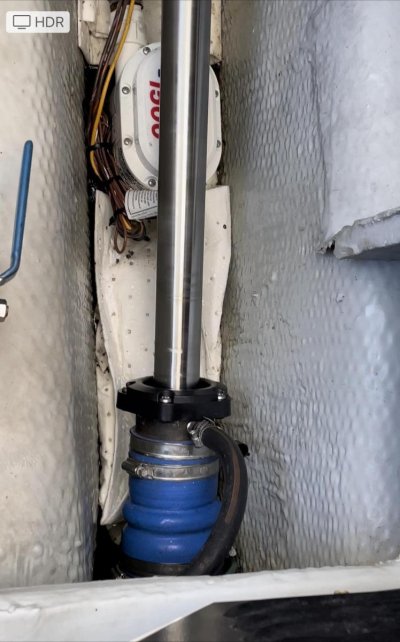
Is this normal? Shaft movement- short video

The friendliest place on the web for anyone who enjoys boating.
If you have answers, please help by responding to the unanswered posts.
How many actual cruising hours (through the water) were traveled before the video?


I’d say about 135. 50 of them were delivery trip at 9.3 kts. We took the boat out and the capn that helped me deliver agreed nothing had changed with the feel of the boat.

He did acknowledge that we did need to try an alignment to deal with the movement.
 
That looks like runout to me. Speed is too low for it to be vibration I would say. Seems you either have a bent/bowed shaft or an eccentric connection to the transmission. I would measure runout at different stations along the shaft fore to aft using a dial indicator. Runout at the transmission flange should be essentially zero, same on the shaft exiting the hub. If not, something is amiss with the coupling. If runout on the shaft at the transmission hub is zero but large on the shaft near your seal, the shaft is bent/bowed. If you measure negligible runout at the seal while turning the shaft by hand, then I would suspect you've thrown a propeller blade and your wheel is WAY out of balance.
 
Nicely put, Adam. I would do exactly what you describe.
 
Before I ask some follow up questions about things related to the shaft seal, is this shaft movement normal? https://youtube.com/shorts/f4H9Zn3c9eI?feature=share

Specifically asking if the shaft seems misaligned or is this normal movement? I never paid attention to it before. Thanks
Mine has had that wobble when I pick up weeds. stop and reverse clears it up for me, If it happens all the time it could be a slightly warped prop not discovered after the grounding. We boat out of Kingston Ontario and every time we go through the River Styx (On the Rideau) we pick up weeds.
 
I’d say about 135. 50 of them were delivery trip at 9.3 kts. We took the boat out and the capn that helped me deliver agreed nothing had changed with the feel of the boat.

He did acknowledge that we did need to try an alignment to deal with the movement.
A thought.
Is the shaft moving the engine/transmission OR is the engine/transmission moving the shaft. There is a little movement for sure.
What if it is aligned at rest but engine revolution causes movement on the mounts, could that occur?
 
I’ve got a run out gauge coming tomorrow. Hoping for some solid data in the next week on what the problem really is and planned solutions.

Thanks all for the advice, will update as I know more!
 
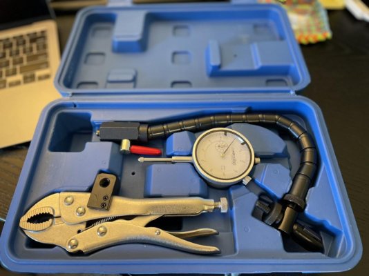
I’ve got the gauge, will be easy to mount on the coupler end by the engine. There isn’t much to mount to on the seal end. Any ideas? Here’s the setup:
IMG_1708.jpg

And it has to mount somewhere down here: IMG_1709.jpg

There’s the through hull valve for the generator right there on the left, I think that may be the only obvious spot.
 
I’ve got the gauge, will be easy to mount on the coupler end by the engine. There isn’t much to mount to on the seal end. Any ideas? Here’s the setup:
View attachment 128737

And it has to mount somewhere down here: View attachment 128738

There’s the through hull valve for the generator right there on the left, I think that may be the only obvious spot.
That oughta work. If the vise-grip doesn't fit the through hull well then a c-clamp
or angle iron hose clamped on it may work for you.
 
Last edited:
I’ve got the gauge, will be easy to mount on the coupler end by the engine. There isn’t much to mount to on the seal end. Any ideas? Here’s the setup:
View attachment 128737

And it has to mount somewhere down here: View attachment 128738

There’s the through hull valve for the generator right there on the left, I think that may be the only obvious spot.

dial indicators have fairly weak springs in them so mounting to that valve or valve handle should be fine. if it's not stable, you'll see it easily. i'd get a length of wood (like a 2x2 or similar) and do a little (gentle) prying when you get the indicator in place to see how much effort it takes to move the shaft laterally as well as taking good readings as you rotate it.
you'll see quite a bit of lateral movement (as measured on the dial) as you pry on it, so don't be surprised by that. it's the way that it moves that's important. if there's easy movement to a point, and then it takes more force to effect more change you'll want to investigate why, and from what area there's play. do this close to the coupler, as well as near the stuffing box.
hard to say if you can figure out a way to measure axial play on the coupler, but as long as you're in there i'd give it a shot. can't have too many data points.
 
I have the more standard magnetic indicator bases, no vise grip holder. Looks like a good setup.

Ok, now to my point. Many times the best way to mount these things, indicator, is a piece of steel, angle or flat , as the situation requires which is itself clamped somewhere nearby.
Look around and you may see a spot to use that a piece of steel can be clamped with a small C clamp of such making a much more stable mounting.

Even a stringer although maybe that will need both an angle and a plate.

Last resort, without clamping, would be a heavy steel plate, 10 lbs or more that will stay put as you play. THe weight would reduce any accidental movement.
 
Last edited:
Even hot glue a piece of wood in place and when you are done scrape the glue off.
 
Whatever setup you use, you can tell if it is working OK if it gives the same readings for each turn of the shaft. (If it returns to the same value after one complete turn)

Do send photos of your setup!
 
Thanks all. Will be a couple days yet before I’m up there.

Seriously can’t tell you all how much I appreciate you!

Will post pics, and maybe even a TF specific video!
 
SHAFT UPDATE! Video and measurements.

Hey all,

Well I'm up here on the boat and got some measurements. You can watch this video for all the data, but will also list below. The 3 minute video - https://youtu.be/x9PfzdJmm54

As described in the video, measured using a run out gauge. I set the gauge, found the bottom and then rotated the shaft.

1- Coupler - 11.5 or 12 thousands of an inch.
2- Shaft after coupler - 11.5 or 12 thousands of an inch.
3- Shaft near seal - 19 or 20 thousands of an inch.

What would you consider normal tolerances for this?

Based on what everyone responded with before, I believe step one would be an alignment. Any thoughts? Thanks

mncruiser
 
Based on what everyone responded with before, I believe step one would be an alignment. Any thoughts? Thanks

Yes, start with alignment. Make sure engine mounts are in good condition first.
.003-.005 would be a good target. When I did my measurements I noticed a significant deflection when I turned the shaft by hand in the middle of the shaft. Find a spot where deflection is minimal and factor in any that you can't eliminate.
 
Last edited:
Assuming you were on the shaft right next to the coupler for the “coupler” measurement then there is a problem at the coupler. If so, no amount of alignment will fix that. You should try to find out why the shaft is wobbling at the coupler first because it could be your entire problem. The most likely causes are: coupler face not parallel to the transmission side coupler face. This could be caused by crap between the coupler faces or a gouge in one of the coupler faces. Or some kind of gouge or other issue between the shaft and the coupler causing the shaft to not ride in the center of the coupler (this happened to me and caused exactly the same symptoms you see and was easy to fix).

Ken
 
Ok, first thing I would do, and because it is the easiest thing to do, is an engine alignment. What diameter is the face of the coupler? If it is, for instance, 6” then you are allowed .006” difference side to side and top to bottom. Less is better though and you should be able to get it to less. Basically.001” per 1” of coupler face diameter.

Then things get more complicated. Not sure I like the 12 thousandths runout on the coupler. But I am not an expert on drive trains. And almost 20 thousandths on the shaft by the stuffing box sounds like a lot, but I don’t know the specs and what is good or bad. But it looks like a lot to me.

I would do the engine alignment first. Then maybe pull the coupler and take it to a machine shop and have them check it out, if the alignment doesn’t fix the problem. I wonder if the output shaft in the transmission could be causing some of the coupler runout. Maybe if you have the coupler off check the runout of the output shaft.
 
First off - nice video mncruiser! Your dial gage setup looks good. One comment - you dont necessarily have to zero the dial indicator - you just have to record the difference between the maximum and minimum readings. Rotate the shaft at least 3 times and check that the difference is consistent.

So what have you discovered?
1 the shaft has excessive runout right next to the coupler
2 the coupler hub has the same runout (I am going to presume that they both hit the max at the same position of shaft rotation)
3 the shaft runout at the seal is almost double what it is at the coupler.

Conclusions:
1 and 2 above mean that the coupler is concentric with the shaft.

What to do next?
Personally, I would suggest doing easy things first.
I suggest:
1 measure runout on the edge of the flange of the shaft half of the coupler
2 measure runout on the edge of the flange of the transmission half of the coupler
3 loosen the coupler bolts and repeat all of these 4 runout measurements
4 post again and lets see what you have

Regards,
Nick
 
that's a lot of runout. i would expect less than .005 at the transmission output flange. radially and axially. .003 or less would be normal. probably the first thing i'd do is disconnect the coupler from the output flange and see what the flange is without the influence of the shaft and coupler. if something is damaged there as a result of the impact the made the shaft replacement necessary, that will need addressed before any additional work is done.
it's funny the yard didn't check that runout when the shaft replacement was done.
 
Runout is excessive.

While it doesn't hurt to check alignment, misalignment does not create eccentric run out, it creates a constant bow, which is not measurable using a dial indicator.

If the run out increases as you get further from the coupling then that points towards a bent shaft.

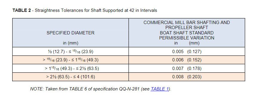
Here are the allowable tolerances for straightness..."ABYC P-6.5.3.2 The permissible variations in straightness of precision straightened, cold finish, round rod and shafting, as determined by the departure from straightness (i.e., throw in one revolution), shall not exceed the indicated values in TABLE 2 when supported on rollers at 42 in (1.07 m) intervals"
 

Attachments

  • Shaft Straightness Tolerances.jpg
    Shaft Straightness Tolerances.jpg
    103.8 KB · Views: 34
I suggest:
1 measure runout on the edge of the flange of the shaft half of the coupler
2 measure runout on the edge of the flange of the transmission half of the coupler
Regards,
Nick


Thanks for the reply. I’m not sure I understand points to measure 1 and 2 that you are suggesting. Can you describe them related to where I already measured in the video?

Thanks
 
I’m not sure I understand points to measure 1 and 2 that you are suggesting. Can you describe them related to where I already measured in the video?

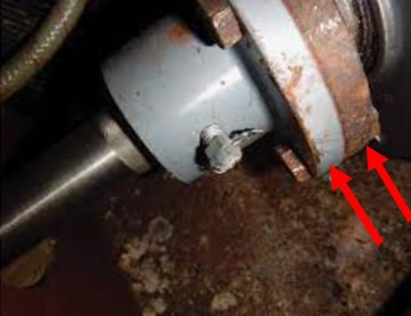
Here is an image which I hope makes it clear. However, if the flange is rusty like the one in the image you may not get a good reading with the dial indicator.

Regards,
Nick
 

Attachments

  • coupling.JPG
    coupling.JPG
    28.4 KB · Views: 22
Thanks for the reply. I’m not sure I understand points to measure 1 and 2 that you are suggesting. Can you describe them related to where I already measured in the video?

Thanks

I don't disagree this coupling measurement can be useful, if you are trying to determine if the eccentricity is the result of a coupling not centered on the pilot bushing.

While there are exceptions, if the run out increases as you move move away from the coupling(s) that is indicative of a bent shaft.

If the shaft is not centered in the coupling, or if the shaft coupling is not centered on the output coupling, the run out is greater closer to the couplings. That does not appear to be the case here, runout is increasing as you move aft, right?

Bottom line, the shaft and coupling should be taken to a shaft shop to have them evaluated. Based on the readings, the likelihood of this being related to the coupling is slim.
 
Thanks for the reply. I’m not sure I understand points to measure 1 and 2 that you are suggesting. Can you describe them related to where I already measured in the video?

Thanks

the measuring points nick shows in the picture are a good starting point. if you see a lot of runout on the output flange, disconnect the shaft and move it aft so the flange is completely free. then re check the flange. also see if you can get enough room to aim the indicator so it can measure the axial runout. (flange wobble)
be sure to do a little light prying with some sort of lever to see how much slop there is.
the spec steve posted with the abyc values are helpful, but may not exactly be germane to your situation as the shaft and coupler have essentially the same measurement. in my mind, the output flange is the place to start.
 
I don't disagree this coupling measurement can be useful, if you are trying to determine if the eccentricity is the result of a coupling not centered on the pilot bushing.

While there are exceptions, if the run out increases as you move move away from the coupling(s) that is indicative of a bent shaft.

If the shaft is not centered in the coupling, or if the shaft coupling is not centered on the output coupling, the run out is greater closer to the couplings. That does not appear to be the case here, runout is increasing as you move aft, right?

Bottom line, the shaft and coupling should be taken to a shaft shop to have them evaluated. Based on the readings, the likelihood of this being related to the coupling is slim.

the runout does indeed increase as you move aft, but the measurement at the coupler is also way too high. the huge bearings at the transmission output should keep that runout to a minimum.
it would seem to me there's more than one thing happening here, and nothing should be overlooked.
 
Looking back at the beginning of the thread, the original problem was a grounding. The shaft was replaced, but that doesn’t ensure that the new shaft is straight, it should be but your runout by the shaft log indicates that it may be bent. I wonder if they checked the strut(s). Unfortunately I think that you will likely have to find a yard that has experience with drive trains and have them start from the beginning and check everything in the system. They can take a laser and sight it in from the back strut and see if the struts are in alignment or not. Better have your wallet ready though.
 
Thanks all for the thoughtful replies.

At this point I’ve exhausted what I can do personally related to skill and time. I’ve got to wait for the marina to get out of spring insanity mode, and take a breath and take some time and look at it.

I think I’ll share my data points with them, but want them to draw some conclusions themselves as to how to resolve.

I have some good data points to start with and am now somewhat informed.

The good news is the boat runs and floats just like it did for 100+ hours last season. Going to come up with a solid plan to remedy this correctly and get boating…..when it hopefully warms to above 48 degrees!

Thanks again all. Will update as I find more out.

Keep us posted on what they find. Unless they immediately find something obvious inside, I'd plan to remove the prop, shaft and coupling and send them to a good shaft shop to check shaft straightness, coupling fit and face, and prop engagement to taper. They should also have a good look at the output coupling face and pilot bushing.
 
Thanks all for the thoughtful replies.
At this point I’ve exhausted what I can do personally related to skill and time.
The good news is the boat runs and floats just like it did for 100+ hours last season. Going to come up with a solid plan to remedy this correctly and get boating…..when it hopefully warms to above 48 degrees!
Thanks again all. Will update as I find more out.

I’m still trying to figure out what the issue is? You have a video of a wiggle in your prop shaft that, as I understand, does not manifest into any disturbance in the operation of your boat going through the water at any speed and absolutely not your sweet and economical 9 knot cruising speed.
Where’s the beef? I must be missing something.
 
Back
Top Bottom