My Short Haul Refit

The friendliest place on the web for anyone who enjoys boating.
If you have answers, please help by responding to the unanswered posts.
Awesome plan, I'm a few more years further out then you, some common plans of where to travel, not looking to do the full loop, northern Canadian canals which we haven't done and maybe the BVI/AVI areas is what we are hoping for.

Thanks again for sharing, all the best! :thumb:

Thought I would do the whole loop avoiding the Mississippi and the Canadian canals. Wanted to see what the other rivers in the central USA were like as some sounded interesting. Think I can live without seeing the levies of the Mississippi. Plan to make a second trip back up the Hudson to see the Canadian waters. Want to be able to spend more time without the traditional imposed deadline of Chicago by Labor Day. Would plan to come down the Hudson in October, follow fall to Florida if that's possible.

Ted
 
"With the large wire size lugs, getting that third lug on the battery terminal is going to be tough."


Yeah, I can see where that would be difficult. I would still consider putting my charger wires there though if at all possible.
 
"With the large wire size lugs, getting that third lug on the battery terminal is going to be tough."


Yeah, I can see where that would be difficult. I would still consider putting my charger wires there though if at all possible.

If you go with Trojans and want bolt on terminals, I would suggest you go with the EHPT (embedded high profile terminial) post. The difference is the ability to stack more than 2-4/0 or 2/0 battery cables per post. With the standard post, the ELPT (embedded low profile terminal) you are limited to ~2. If you look at the lower right terminal, I have 1-4/0 and 2-2/0 lugs on the post. I would like to have a little more post height. It's an ELPT.

When we picked up our batteries, the seller went out of his way to stress that we use the correct torque for the nuts on the posts. He showed us 2 new batteries where a buyer (s) got a little carried away over tightening the nuts. Trojan lists the torque value at 95-105 in-lb for the ELPT or EHPT posts.
 

Attachments

  • Battery Cables 002.jpg
    Battery Cables 002.jpg
    122 KB · Views: 147
Yes, a Victron battery monitor, shunt is in the 6th pic of post #83. Plan to use it as a rough guide for state of charge, and reset it each time the bank is completely recharged. Really more interested in amps out and amps in rates as opposed to state of charge of the bank. Working under the assumption that when amp flow in drops to almost zero after many hours of cruising, the bank is close to fully charged, and the 220 amp alternator is producing for current consumption only. Does that sound like a viable plan?

Ted

Sounds good. We also look at the amps in/out the most. We do look at the voltage but more as an indicator when we aren't charging. From experience, I can tell the SOC pretty close even if the batteries aren't at rest by what the voltage is and what's running DC wise.

Great thread.
 
Ted: You know, going with the little Deere is going to ruin your wake-making possibilities. Still, that 3.5" shaft must be a record for that size motor....giving you the "my shaft is bigger than your shaft" bragging rights at the anchorages. I want that boat, Ted. I don't care if it costs a million bucks, I want it.

Note: I can't do anything about it, but I want it.:)

Lusting over another's boat, one of the 7 deadly Trawler Forum sins. Well at least you're open about it. Is Bucky ok with this? :nonono:

Ted
 
Dimer... You may want consider this connection set up for where you come off the bank.

Can certainly see how it's theoretically better. Wonder if there is much of an actual difference?
Ted

Ted... I just stumbled across your thread and got "caught up" w/ the work. Nice job w/ the refit - great looking vessel - thanks for taking the time to document & share it.

Re: the above comments - I have also wondered just how much better the theoretical connection would be. I started a Reference material thread in the Electrical Electronic & Nav sub-forum Post #9 includes a link Smart Gauge How to correctly interconnect multiple batteries to form one larger bank.

This is the best explanation & quantification of the differences of several battery wiring alternatives... hope it helps

Hi Don, appreciate the link. The 15% difference in draw down isn't huge, but it is significant. The stumbling block for me is still getting that 3rd cable on the battery terminals and routing the wire within the battery box. Things would be a lot easier if I had made the box bigger. Lots of fun bending 2/0 battery jumpers in tight spaces.

Ted
 
I need another refit FIX. Its been two weeks.
 
I need another refit FIX. Its been two weeks.

Me Too...
I was really looking forward to seeing how the glassed over cap rails turned out when completed. :popcorn:
 
Hi Ted & Miss Cotton 11.

Thank You for an amazing thread, there is so much here for anyone who loves Messing Around in Boats.

Your dedication to your vessal is inspiring.

Thank You Sir.

Regards.

David.
 
Hi Ted & Miss Cotton 11.

Thank You for an amazing thread, there is so much here for anyone who loves Messing Around in Boats.

Your dedication to your vessal is inspiring.

Thank You Sir.

Regards.

David.

I need another refit FIX. Its been two weeks.

Me Too...
I was really looking forward to seeing how the glassed over cap rails turned out when completed. :popcorn:

Many thanks for the kind words. Clearly I have been slacking in my responsibilities to the forum. Will add some more pics later. Step daughters families are in town to celebrate the two year old's birthday. 35 adults and children are expected in our 1,800 sqft. house. :nonono: I will be heading to the solitude of the boatyard till the "all clear" text is received from the admiral.

Ted
 
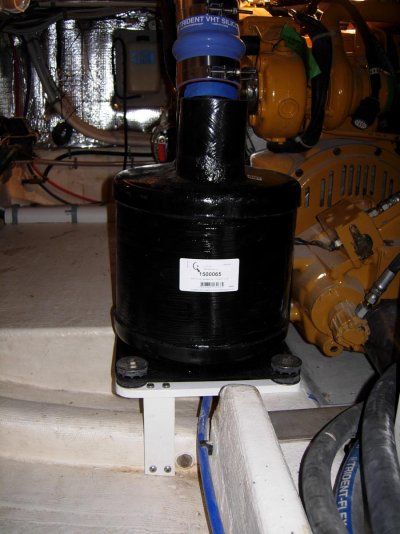
So I’ve been home from FL for 2 weeks and maybe spent half that time in the boatyard. Holidays and family obligations have been keeping me home. Spring has come to the boatyard with the waterman changing over from oystering to crabbing, the charter boats and the recreational crowd getting ready for summer. That means Sean’s time gets divide between his regular customers and me. So not a whole lot has gotten done. Here are a couple of projects from this week. The exhaust riser and lift muffler didn’t turn out exactly as planned. Near as I can tell the lift muffler intake isn’t in the same spot as the drawing. 2 inches is everything. Had to raise the exhaust riser, then cut the muffler intake on an angle, and finally glass a fiberglass tube extension to mate to the exhaust riser. Sean did the glass work and as expected it looks better than factory. Here is the riser in the original position:

DSCN1093.jpg

The riser, lift muffler with extension, and brace installed:

DSCN1150.jpg

The base for the lift muffler is coosa board wrapped in fiberglass. The one support is made of ¾” starboard. The muffler is separated from the base with Sound Down isolation mounts to reduce vibration and noise.

DSCN1152.jpg

Looking down from the top. The Stainless Steel plate laying across the engine bed in front of the genset will be a bridge for the water heater loop hoses and the raw water pump feed hose.

DSCN1154.jpg

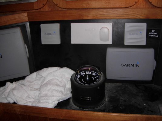
Pardon my dust. In spite of best efforts, there is dust everywhere, and I’ve just given up fighting it. Added 3 Garmin GMI 20 displays. They tie to the NMEA 2000 network with only one cable which also supplies power to the display. 2 are here in the pilot house.

DSCN1163.jpg

The third display is in the master stateroom next to the bed.

DSCN1157.jpg

DSCN1158.jpg

The display can utilize any of the information on the NMEA 2000 network. So it will display GPS position with an anchor watch and alarm, heading sensor to show orientation of the boat, depth, wind speed, wind direction, and outside temperature. The plan is to have it continuously scrolling through several screens: anchor plot with drag alarm, depth with minimum depth alarm, and wind speed with direction. Hoping I can dim the display enough to keep it uncovered at night. Like the idea of being able to check conditions without getting out of bed. Leaving the display and network on should draw less than 2 amps.

DSCN1159.jpg

Too many toys. Stop me before I buy again.

Ted
 
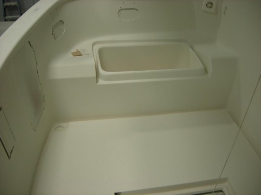
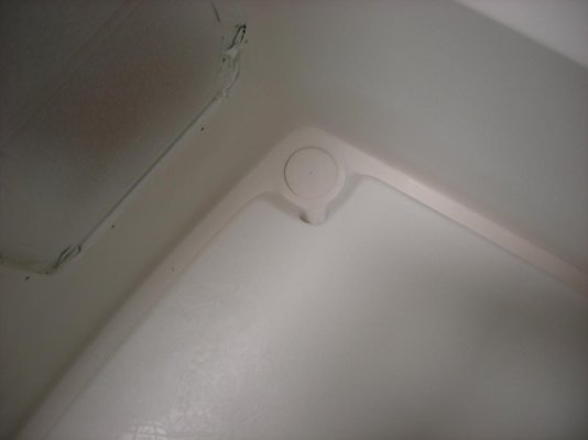
Here are some more pics from the Ultra Build priming. Inside the back deck has not been final sanded yet. This is looking to port on the inside of the back deck. Notice the guttering going around the deck and from the center hatch.

DSCN1130.jpg

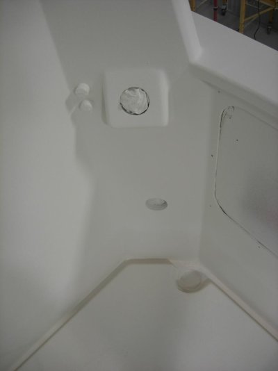
The new fuel filler mounting block with covered vents.

DSCN1129.jpg

The floor guttering with port rear floor drain.

DSCN1131.jpg

Rear deck looking to Starboard.

DSCN1148.jpg

Starboard fuel filler block, vents, shore power receptacle hole, and forward floor drain.

DSCN1133.jpg

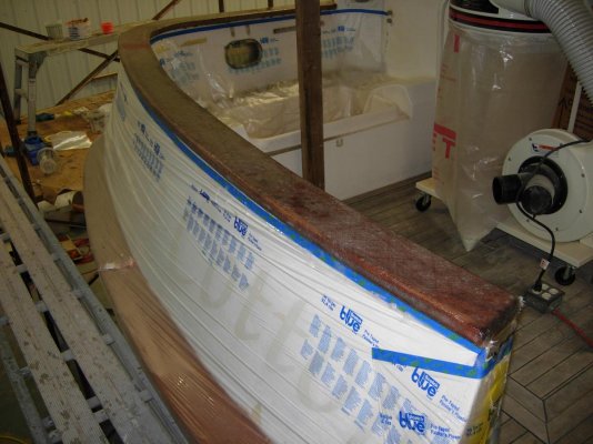
Before pics of the cap railing getting bi-axial cloth and West System encapsulated.

DSCN0869.jpg

The railing with West System Frosting.

DSCN0877.jpg

The railing sanded, primed, Ultra Builded, and mostly sanded.

DSCN1135.jpg

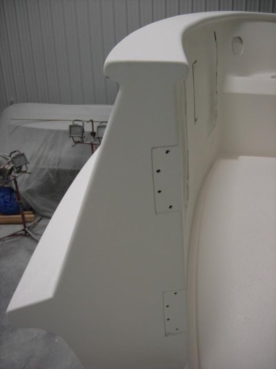
This is the transom door complete except for final prime and top coats.

DSCN1141.jpg

Hard to tell this wasn’t one molded piece.

DSCN1142.jpg

Purdy work! :)

Ted
 
Great work Ted. I love the cap rail look. Transom door is stunning- I also like the "plug" for the rear access hole!


1983 Present 42 Sundeck
Twin Lehman 135's
✌️
 
Awesome workmanship!! You're going to have a better than new boat when your done.
I was wondering if you were going to paint a contrasting color for the cap rail, but it looks great just like it is!
 
Gotta admit to having trouble picturing the cap rail encapsulated in my mind but there's no arguing with the pictures, looks great. Huge improvement to the look IMO and eliminated the ongoing maintenance too. Win-win solution.
 
Awesome workmanship!! You're going to have a better than new boat when your done.
I was wondering if you were going to paint a contrasting color for the cap rail, but it looks great just like it is!

Still pushing that around. The hull will be "Ice Blue" which is a very light tint. Everything above the cap rail will be "Matterhorn White". The boot stripe and likely the cap rail will be a dark blue. The hull and top side colors need a separation. So the boot stripe color looked to be a good choice. Both the rub rail and the cap rail have a stainless steel guard that runs on the outside. So it will likely be ice blue below the guard and dark blue above the guard.

Ted
 
Nice work on the exhaust, I like the rod support, you'd be surprised at the vibration that would have and the fatigue it would create without it.
 
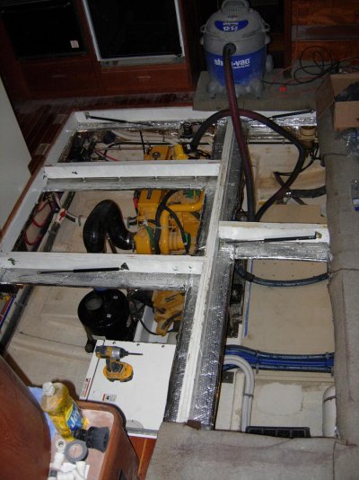
Monday the floor grid went back into the boat. Have reached the point where almost all the remaining work in the engine room in some way requires the grid to be in place. A number of items are attached to the floor beams, such as the exhaust pipes, fuel and return lines to the engine, wiring harness and coolant line to the expansion tank. The down side is that there is now a lot more crawling and the occasional up, out, over, in, and down to get to the other side. The good news is that the end of the engine room work is in sight…..hopefully.

DSCN1165.jpg

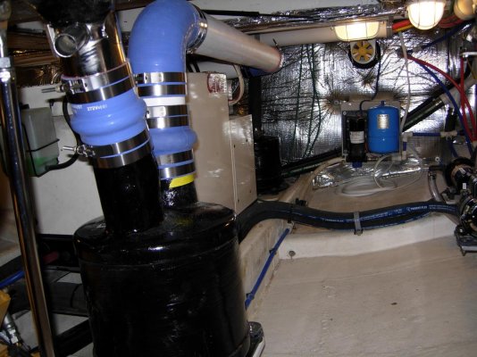
With the grid in place, one gets a sense of how high the exhaust elbow ended up being. The floor above the elbow is under the kitchen island. Had already planned on reworking the sound insulation underneath to accommodate the elbow. The elbow is dry until after the black heat wrap where the water is injected into the stainless steel pipe that is sticking out. Should make it very difficult for water to get back to the turbo.

DSCN1175.jpg

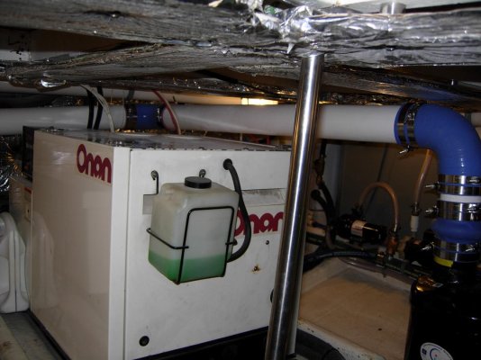
Finished the hose bridge in front of the generator. Lots of hoses to lay out and make look somewhat organized. In the picture, the white hoses are for the 2 rear bilge pumps; blue hoses are for genset, engine, and transmission oil change system; black hoses are raw water for genset, air conditioner pump, anchor salt water washdown and engine to water heater coolant loop.

DSCN1182.jpg

There are 3 areas around the engine where hoses or electric cables have to run across the engine room floor directly under overhead hatches. To avoid damaging them the hoses and cables will be secured in place and covers made of Coosa board, 2 layers of bi-axial cloth with fiberglass, and gel coat. They will be screwed down over the hoses and cables. The covers are now being gel coated, so no pic of them, but this gives you an idea of what the hoses crossings will be like under the cover.

DSCN1185.jpg

The exhaust system is essentially done. Just need to fabricate a couple of Stainless Steel hangers to replace the braided line that is currently holding the pipes up. The pipes are all fiberglass exhaust tube that was lightly sanded and given 3 layers of gel coat. Very happy how this turned out. The exhaust no longer blocks either side of the engine or genset. The pipe drops at least 1” every 2’ from above the lift muffler till it exits the transom. Easy access to the generators port side was maintained.

DSCN1210.jpg

Looking at the exhaust system from the starboard side toward the port side of the boat.

DSCN1214.jpg

Down the side and across the back.

DSCN1215.jpg

The one compromise in the exhaust run was crossing over the house battery bank box. The lid comes off easily and there is still plenty of room for watering and servicing connections. Would have prefer to have routed it differently, but there just wasn’t a better all around choice.

DSCN1216.jpg

The corner became tighter than originally planned. Getting to the Vacuflush pump now requires lying on the battery box cover and working over the exhaust pipe. Knew it was going to be more difficult to work on the pump when I mover it there, so I installed pvc pipe unions on both sides of the pump and rebuild everything but the motor before reinstalling it. The plan is to remove the pump to do preventative maintenance. Installed a valve just after the pump to ease removal.

DSCN1217.jpg

This is a tease for the next post.

I lived for 20+ years on Delmarva which has a great deal of farming and commercial fishing both in the Chesapeake and the Atlantic. In a rural area with thousands of small business, specialty companies thrive. One such company is Billy Warren and Son. A Google search will list them as a salvage or junk yard. Billy and his family have made a business out of buying companies and yards that are going out of business or need to liquidate inventory. Simply if you need Stainless steel or aluminum: plate, diamond plate, sheet metal, perforated sheet metal, flat stock, angle, channel, round stock, square stock, box tubing and just about and any fabrication stock, they have it. Almost all of it is in racks and on the ground outside. You wonder though the racks and find what you’re looking for. They will cut lengths to whatever size you need. Most of the short cut off pieces are sold at scrap price per pound. Everything is a deal; the short pieces on the ground are a steal! They also have trailers full of stainless fittings hardware and a bunch of mil spec stuff that your tax dollars bought and Billy paid pennies for. This is where the boatyard and I go for all our stainless steel material needs….Stainless Steel scrounging paradise. They also have a sense of humor there. The hacksaw in the below picture will give you a size reference for the massiveness of that piece of “I” beam. The note says,"Self Service". :lol:

Billy Warren.jpg

Ted
 
Last edited:
My Raw water project:

When I bought the boat, there were 5 below water line plastic seacocks.

1.
Engine cooling
2. Generator cooling
3. Generator cooling water after exhaust separator discharge
4. Air conditioning / heat pump raw water
5. Holding tank over board discharge

Two seacocks were in bad locations to access. One was directly under one of the engine room access hatches (easy to step on). Two were located in nice storage spaces that you couldn’t then utilize as the contents would be piled on top of the seacocks, making them inaccessible in an emergency. The first goal was to reduce the number of seacocks. Second was to locate them in easily accessible locations that didn’t waste premium storage space. Third was to relocate the AC pump, strainer and seacock to the engine room. It had been previously located under a bunk in the guest stateroom and was anything but quiet. Forth was to add a raw water wash down pump for anchor retrieval. Fifth was to build a water cooled dummy load for my genset.

The over board discharge seacock for the holding tank was moved from a prime location for storage through the hull of the lazarette to the lowest center point of the transom behind the rudder post. The plastic seacock was replaced with a bronze through bolted seacock tied in to the hull bonding system. All removed seacock holes were dish ground out inside and out. Then the dished areas were filled with a minimum of 4 layers of progressively larger bi-axial cloth circles with West System epoxy. So each hole was filled with 8+ layers of cloth and epoxy. They were then faired and coated with 3 applications of gel coat inside and out.

The genset exhaust water seacock was removed and the hole filled. The 4” engine exhaust, the 1.5” genset gas exhaust, and the 1.5” genset water discharge now all exit through a single 6” exhaust through the transom.

The AC water pump was relocated to the engine room. The seacock was removed and the hole filled. The genset raw water seacock was removed and the hole filled. The 2” plastic seacock for the engine was removed. It was replaced with a bronze 2” through bolted seacock tied into the hull bonding system. What remained was to feed all the raw water system (AC pump, engine, genset, and anchor wash down pump) off this 2” seacock…..and the water cooled dummy load for my genset.

There have been several threads on genset loading and some amount of varying opinion. Most manufactures recommend somewhere between 25 and 50% load all the time to make the genset engine run at proper operating parameters. Not really interested in debating the issue or percentage again. My genset service center recommends a minimum of 25% all the time. Typically that can be accomplished by running the heat / air conditioning whenever the genset was on. Simply, I want to be able to run my 8KW genset whenever I want without turning on systems to provide an adequate load. My solution was to build 2 dummy loads. These are 1,000 watt immersion heating elements built into the raw water cooling system of the genset. Each element is on one power leg of my 220 volt genset and is turned on by flipping a breaker at the electrical panel. If I received $1 per hour for the time I have invested in this project, well it would likely cover another generator. But as I’m sure everybody knows, when it comes to our boats, sometimes you start on a project and in spite of common rational sense you just can’t let it go. So what follows is my obsession; sure hope it works as anticipated.

This is the external strainer that mounts on the hull. The screen is 9” by 4” and will support a 3” seacock flow. Absolutely the best system for keeping debris from clogging your raw water system.

DSCN1222.jpg

My new 2” seacock and 2” Groco strainer.

DSCN1191.jpg

If you look carefully, you can see a plastic strainer basket. If you maintain a near constant flow through a Stainless Steel basket, the electrolysis will eat through the basket (my AC strainer basket had corroded in two). Groco recommends this for AC service and the holes are smaller than the outside strainer for finer filtration.

DSCN1190.jpg

This is my masterpiece or windmill depending on how you want to look at it. The distribution box is made out of ¼” thick 5” square stainless steel box tubing. The end plates are ¼” thick stainless steel plate. All the connections are made with weldable couplings. These are stainless steel rings that are tapped for pipe thread on the inside and can be welded on the outside. All the stainless material, pipe fittings, valves, and hose barbs were sourced from Billy warren and Son for less than $100. There is a welding shop in Crisfield that can make just about anything for a work boat or a yacht….at very reasonable prices. They plasma cut all the parts and holes, TIG welded everything together, and then polished it to an almost mirror finish (8 hours of polishing) (I think $400 total).

Raw water (2”) enters on the left. Engine feed (1.25”) is from the bottom. Genset feed (1”) is from the top valve on the right. AC pump and wash down pump feed (1”) is from bottom valve on right. The top of the distribution box is between 4 and 8” under sea level. So the box has a positive feed pressure.

DSCN1205.jpg

Bottom of the box has a ¾” mpt pencil zinc that is 4” tall to eliminate electrolysis. The box is also tied to the boat’s bonding system along with the strainer and seacock.

DSCN1225.jpg

The two 1,000 watt stainless steel immersion heaters were probably the hardest thing to source. They are all Stainless with a 1” mpt. They are used to keep oil in tanks warm during the winter on trucks and equipment in frigid environments. They are made by the largest block heater manufacturer, but for some reason, not well advertised. Cost about $70 each. They are almost the full length of the distribution box.

DSCN1224.jpg

On top of the box are 2 water heater thermostats set around 90 degrees. In the event that the heat elements accidently get turned on while hooked to shore power with no water flow, the thermostats will turn off the heaters when the water reaches 90 degrees, saving the elements.

DSCN1075.jpg

The thermostat cover is another Sean custom fabrication. Did I tell you he does really nice fiberglass work?

DSCN1228.jpg

Here is the transmission cooler mounted on one of my custom built Stainless brackets. What’s note worthy on this is that John Deere wants the gear cooler before the water pump. So the tube bundle inside the heat exchanger needs to be much larger in diameter to maintain high flow volume. I installed a pencil zinc at the bottom of the right side, barely visible.

DSCN1202.jpg

Here are the wash down pump (on left) and AC pump (on right).

DSCN1229.jpg

With all the pumps running at full speed, the absolute flow total would be about 58 GPM through the 2” seacock. The Cummins 450 that came out had a flow requirement of 60 GPM through a 2” seacock. My expected peak flow at cruise speed with the genset and AC on will more likely be around 35 to 40 GPM. Wash down pump likely will only be running when the engine is idling, etc. The 2 heating elements will add about 4 degrees of heat to the 6 GPM flow rate of the genset, not an issue.

Ted
 
Ted,

Thank you for the detailed descriptions, plans, thinking and photos. That's a lot of work in and of itself.

I think your engine re-power will pay you back sooner than you realize. Kadey Krogen is pretty straight with their numbers, so with the numbers you mentioned, I would think you will be very close to 1.8 gal/hr at 7 knots.

Good luck and getting her done soon.

Thanks again.
 
Man....I'm blown away by your detailed planning, Ted. The fact that you are managing to carry the plan through to the final product is pretty amazing. Superb work!
 
Ted,

Thank you for the detailed descriptions, plans, thinking and photos. That's a lot of work in and of itself.

I think your engine re-power will pay you back sooner than you realize. Kadey Krogen is pretty straight with their numbers, so with the numbers you mentioned, I would think you will be very close to 1.8 gal/hr at 7 knots.

Good luck and getting her done soon.

Thanks again.

Hi Richard,

Have enjoyed the process.......most of the time. When it's done, if it's not the way I want it, I have no one to blame but myself.

Would be very happy at 1.75 GPH = 4 MPG.

Ted
 
Man....I'm blown away by your detailed planning, Ted. The fact that you are managing to carry the plan through to the final product is pretty amazing. Superb work!

Thanks Larry,

The enthusiasm for the project is waning.....ready to be done and out cruising. Fortunately, my jobs are about 90% done. Daily work is now about completing projects, not starting new ones.

Ted
 
OK good chance I missed a chapter, so I apologize if this was discussed, what are you using the heaters in the raw water distribution box?

All works is amazing, not sure 100% on-board with the raw water wash-down and AC pump setup, some of those plastic to metal fittings could have load on them and fatigue and given it's below the waterline could cause a problem.

Hi Mike,

The heaters provide a power load on the generator of each 1,000 watts or combined 2,000 watts (2 KW). If I want to run the generator for a couple of hours at anchor to partially recharge the house battery bank, the load is marginal on the genset. Turning on the heaters allows me to increase the total load to just under half of the generator's capacity. Most generator manufacturers want their units run with a minimum of 25 to 50% load.

The hoses on the pumps are pretty flexible with curves built into the layout to reduce stress. As most pumps for these applications are made of plastic with plastic fittings, I don't think this will be a problem. It's very common to see plastic and metal fittings combined on water pump systems.

Ted
 
OC beautiful work indeed. The spill over point of the wrapped exhaust doesn't look much higher that the outlet of the water lift. I suggest care similar to that used with a genny if the engine doesn't fire up immediately.
 
OC beautiful work indeed. The spill over point of the wrapped exhaust doesn't look much higher that the outlet of the water lift. I suggest care similar to that used with a genny if the engine doesn't fire up immediately.

Hi Bayview, appreciate the concern!

The picture and the epoxy wrap give a deceptive impression. The stainless pipe inside the wrap is only 3.5" OD. The bottom of the peak of the stainlees pipe is over 4" above the spillover point to the fiberglass tube after the lift muffler. Much of the Stainless steel pipe is above the sound insulation that the fiberglass tube is below. Absolutely, agree about start up care. Both the genset and the main are setup with drains on the lift mufflers. On anything but an instantaneous start, the drain would be opened and only closed after startup. Diesels don't like back pressure when trying to start.

Ted
 
Hi Mr. O C DIVER!

I've been following your magnificent re-engineering and refit from afar.

I finally had to join to inquire as to whether you have all the loose ends wrapped up?

Thanks!

Riley
 
Back
Top Bottom