Marco Flamingo
Guru
- Joined
- Jan 7, 2020
- Messages
- 1,111
- Location
- United States
- Vessel Name
- CHiTON
- Vessel Make
- Tung Hwa Clipper 30
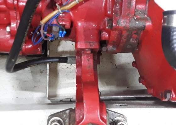
I wanted to examine my damper plate after getting a little saltwater in the flywheel casing (another thread). My 80 hp Lehman has front motor mounts on the block and rear mounts via cast iron "swan neck" arms on the Velvet Drive transmission (picture below). I'm not sure if this setup is used on the 120 hp Lehman, but it is common on the 80 hp. In order to remove the tranny, it is necessary to put temporary mounts on the back of the engine block. The prior owner left some "official" Lehman rear motor mounts onboard. They are heavy welded steel and setup to use a motor mount, which I didn't need to temporarily hold the weight of the rear of the engine. Because there are no actual rear dampers mounted on the stringer, they would require considerable shims.
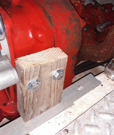
So I made some simple wood blocks. My engine block sits very close to the engine stringers, so 2x4” scraps were sufficient. The bolt pattern on the rear of the block is a square (4 holes 2x2” OC), but I only used 2 holes in the 2x4. I cut them so that they were very close to the stringer, maybe 1/16” off. Then I could use plastic composite window framing shims to adjust and hold the weight (picture below). Sorry there aren't more pictures, but I was busy and my hands were grimy.
First, I disconnected the shaft and slid it back 4 inches (hoping that it would be as easy to slide forward.) I then used a 48” 2x4 as a dead man above the transmission floor hatch. Both ends of the dead man were on towels to protect the floor and allow me to slide the tackle back when the +150# transmission was disconnected. I used the 5:1 tackle that I use to hoist our dinghy onto the swim step and put a substantial lift on the transmission. This took enough pressure off the temporary wood rear motor mounts such that I could drive the shims in further. Probably a lift of only 1/16”, but I then knew that the transmission could be removed without worrying about any engine weight involved.
My tranny mounts are “swan neck” cast iron pieces (partially shown to the right in the second picture below, but now not as rusty). Since I knew that the weight of the block was held by the temporary shim and the weight of the tranny was now held by the block and tackle, I unbolted the cast iron swan neck tranny mounts at the tranny. That allowed me to then remove the top bolt on the mount arm and lift the arm up off of the damper. My hope was that I hadn’t changed anything and once reassembled I would have no/little engine alignment issue.
I unbolted the transmission adapter plate (the big plate, not just the Velvet Drive transmission.) That’s because I was interested in looking behind the flywheel/damper plate, not just removal of the transmission. As I removed the bolts, I put in 6” threaded rod top, bottom, and opposite side from where I intended to remove the damper plate. Loosening the tension on the block and tackle a little, I was able to slide the dead man back, which allowed me to slide the 200# of tranny and adapter plate back, being controlled by the threaded rod so that it didn’t drop or swing out of alignment.
And there was my damper plate that I was concerned about. I pulled it out and was able to see that the saltwater intrusion hadn’t hurt anything. Only a couple small specks of rust. The prior owner had the engine rebuilt 500 hours ago and the damper plate was clearly replaced then. It had the weird pink paint on the springs like those plates available from Fred Warner, a local supplier. I inspected and cleaned out the whole flywheel casing (which was my main objective), and then coated/wiped everything down with a thin coat of ATF, since I had rags with ATF on them (from draining the tranny prior to the whole operation). I did the same to the damper plate and decided not to replace it. I’ll keep the new(er) one as a spare.
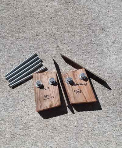
Everything slid back into place with only one problem. While I had the cast iron tranny mounting arms out, I painted them (and a lot of other parts). I didn’t keep track of port and starboard arms because they appeared identical. After putting the tranny adapter plate back on and both tranny mounting arms, I couldn’t get one bolt back in on the starboard arm. Turns out the cast iron arms had been milled, but not identical. There was a 1/16th difference and that was enough so that a bolt would not line up. That added 30 minutes to the project. But, once back together I checked alignment and couldn’t get a .0015 feeler to slip in when rotating the shaft connection. I’ll have to check (everything) after a few hours motoring, but it looks good.
A lot of work for basically nothing. Except for two things. I now know the exact condition of my damper plate (not many can say that). I also now know that I can field service the damper plate by myself. Just think if I could Shanghai a helper! It would cut the time at least in half. I don’t climb in and out of the engine bay (150 times a day) as fast as I used to. Probably the biggest benefit is that I now have onboard a simple damper removal kit. Not shown is a ¾” wrench (ATF line removal and top motor mount bolts), 5/8” socket (adapter plate), and ½” socket (damper plate), 5:1 block and tackle. Damper plate failure is one of the main reasons some claim that two Lehmans are required. Instead of a second engine, I now have this kit.")
So I made some simple wood blocks. My engine block sits very close to the engine stringers, so 2x4” scraps were sufficient. The bolt pattern on the rear of the block is a square (4 holes 2x2” OC), but I only used 2 holes in the 2x4. I cut them so that they were very close to the stringer, maybe 1/16” off. Then I could use plastic composite window framing shims to adjust and hold the weight (picture below). Sorry there aren't more pictures, but I was busy and my hands were grimy.
First, I disconnected the shaft and slid it back 4 inches (hoping that it would be as easy to slide forward.) I then used a 48” 2x4 as a dead man above the transmission floor hatch. Both ends of the dead man were on towels to protect the floor and allow me to slide the tackle back when the +150# transmission was disconnected. I used the 5:1 tackle that I use to hoist our dinghy onto the swim step and put a substantial lift on the transmission. This took enough pressure off the temporary wood rear motor mounts such that I could drive the shims in further. Probably a lift of only 1/16”, but I then knew that the transmission could be removed without worrying about any engine weight involved.
My tranny mounts are “swan neck” cast iron pieces (partially shown to the right in the second picture below, but now not as rusty). Since I knew that the weight of the block was held by the temporary shim and the weight of the tranny was now held by the block and tackle, I unbolted the cast iron swan neck tranny mounts at the tranny. That allowed me to then remove the top bolt on the mount arm and lift the arm up off of the damper. My hope was that I hadn’t changed anything and once reassembled I would have no/little engine alignment issue.
I unbolted the transmission adapter plate (the big plate, not just the Velvet Drive transmission.) That’s because I was interested in looking behind the flywheel/damper plate, not just removal of the transmission. As I removed the bolts, I put in 6” threaded rod top, bottom, and opposite side from where I intended to remove the damper plate. Loosening the tension on the block and tackle a little, I was able to slide the dead man back, which allowed me to slide the 200# of tranny and adapter plate back, being controlled by the threaded rod so that it didn’t drop or swing out of alignment.
And there was my damper plate that I was concerned about. I pulled it out and was able to see that the saltwater intrusion hadn’t hurt anything. Only a couple small specks of rust. The prior owner had the engine rebuilt 500 hours ago and the damper plate was clearly replaced then. It had the weird pink paint on the springs like those plates available from Fred Warner, a local supplier. I inspected and cleaned out the whole flywheel casing (which was my main objective), and then coated/wiped everything down with a thin coat of ATF, since I had rags with ATF on them (from draining the tranny prior to the whole operation). I did the same to the damper plate and decided not to replace it. I’ll keep the new(er) one as a spare.
Everything slid back into place with only one problem. While I had the cast iron tranny mounting arms out, I painted them (and a lot of other parts). I didn’t keep track of port and starboard arms because they appeared identical. After putting the tranny adapter plate back on and both tranny mounting arms, I couldn’t get one bolt back in on the starboard arm. Turns out the cast iron arms had been milled, but not identical. There was a 1/16th difference and that was enough so that a bolt would not line up. That added 30 minutes to the project. But, once back together I checked alignment and couldn’t get a .0015 feeler to slip in when rotating the shaft connection. I’ll have to check (everything) after a few hours motoring, but it looks good.
A lot of work for basically nothing. Except for two things. I now know the exact condition of my damper plate (not many can say that). I also now know that I can field service the damper plate by myself. Just think if I could Shanghai a helper! It would cut the time at least in half. I don’t climb in and out of the engine bay (150 times a day) as fast as I used to. Probably the biggest benefit is that I now have onboard a simple damper removal kit. Not shown is a ¾” wrench (ATF line removal and top motor mount bolts), 5/8” socket (adapter plate), and ½” socket (damper plate), 5:1 block and tackle. Damper plate failure is one of the main reasons some claim that two Lehmans are required. Instead of a second engine, I now have this kit.
Attachments
Last edited: