Morse Control Shifter Parts

The friendliest place on the web for anyone who enjoys boating.
If you have answers, please help by responding to the unanswered posts.

cdsailor

Veteran Member
Joined
Sep 16, 2017
Messages
70
Location
USA
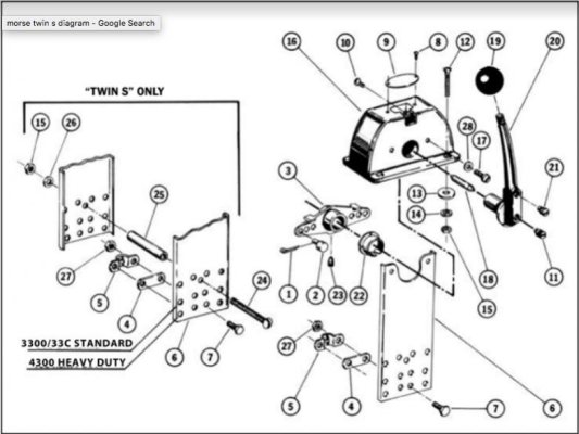
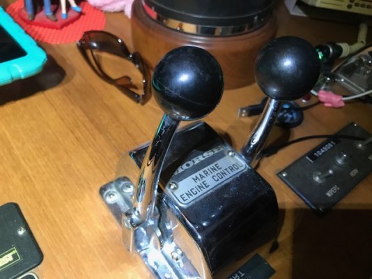
Does anyone have a lead on replacement Morse parts, specifically the internal bronze arms? I’ve got wear where the shifter/throttle cables attach to the control arms, and I’d like to replace them.

Anyone have experience with this?

Thanks. IMG_9002.jpgIMG_8990.jpg
 
You can find complete units in most larger marine consignment shops.
Might be the way to go if you cannot find parts.
 
You could also try finding a bushing that fits. Get the measurements of the hole and the diameter of your cable connection. Should relatively inexpensive as well.
 
You could also try finding a bushing that fits. Get the measurements of the hole and the diameter of your cable connection. Should relatively inexpensive as well.

SMART idea!
 
If the wear is not even, you will have to ream the holes out so they are circular, then find and fit a bushing in. There doesn't look like there is a lot of "meat" there to ream out larger. Have you considered using silicone bronze welding wire, or rod and filling in the holes? Then drill and ream to the desired diameter, stronger than using a bushing. Running silicone bronze in a mig welder, I found it splatters less and goes on smooth if you use Tri-mix instead of straight argon, or argon/CO2. Pretty simple repair from the looks of it.
 
If the wear is not even, you will have to ream the holes out so they are circular, then find and fit a bushing in. There doesn't look like there is a lot of "meat" there to ream out larger. Have you considered using silicone bronze welding wire, or rod and filling in the holes? Then drill and ream to the desired diameter, stronger than using a bushing. Running silicone bronze in a mig welder, I found it splatters less and goes on smooth if you use Tri-mix instead of straight argon, or argon/CO2. Pretty simple repair from the looks of it.

If I can't find a part for cheap, I was thinking about filling the holes and redrilling. Thanks.
 
Personally I wouldn't spend money on Morse parts, I'd buy Kobelt controls which in my opinion are vastly better.
 
I have what appear to be the same controllers (Morse) as cdsailor. My port controller on the flybridge is now quite a bit harder to operate than my starboard side. The difference is hardly noticeable from the lower helm. Noticable if you are watching for it, but hardly. On the upper helm there is much greater difference.

I am hoping it is the cable (17ft Morse 33c with part # 9E23NTM stamped on it) that runs from the flybridge control to the lower helm.
We are in Marathon and it's going to be windy the next few days so this is a good time to pull it apart and take a look. Would anyone happen to have a diagram of the Morse controllers? Before I pull it apart, I would love to see a diagram so I can see what I am getting in to.
 
AZ2Loop,

They're pretty straight forward. I completely disassembled mine, cleaned and lubed them, and just yesterday reinstalled them with all new cables.

This diagram shows a single, but the dual control is assembled the same way.

Let me know if you have any questions. Happy to share what I learned.

David
 

Attachments

  • Screen Shot 2020-03-08 at 8.32.27 PM.jpg
    Screen Shot 2020-03-08 at 8.32.27 PM.jpg
    53.6 KB · Views: 74
cdsailor, that is a great start. Yes mine are twin engines, but that does help. Thank you for the diagram!

Here are a couple of pictures of mine. Does anyone know what the screw labeled "screw #1" (in my picture) does? It would be #21 in cdsailor's diagram. From looking at it, it seems it goes into nothing, but it must serve some purpose.
cdsailer, did you see what that screw does?

Screw #2 (in my photo) would seem to simply hold the shift lever onto the horizontal post that rotates to apply the pressure to push or pull the cable through the sleeve. However, when I turn to loosen screw #2 it seems to move out, and then back in a little, as if there is more to it than simply attaching the lever to the working part of the control unit. Loosening the left side lever's screw #2 also seems to loosen the opposing lever on the right side, yet it has its own screw in the same position. I assume there is some kind of "detent" internally in the controller that helps you feel neutral as you move the levers, but it is not visible of course. I guess I will find it when I dismantle it. Maybe item 3 or item 22 from cdsailor's diagram is the detent?

Thanks for any thoughts and thanks cdsailor for your help so far.
 

Attachments

  • Morse controls gears lower helm.jpg
    Morse controls gears lower helm.jpg
    110.8 KB · Views: 31
  • Morse lever close up 2 screws marked up.jpg
    Morse lever close up 2 screws marked up.jpg
    82.5 KB · Views: 44
  • shifter cable numbers from upper helm to lower helm.jpg
    shifter cable numbers from upper helm to lower helm.jpg
    79.2 KB · Views: 35
Honestly it's so simple if you need a diagram you probably shouldn't be messing with it.
 
Screw #1 is for the detent kit, which you do not have. The detent plate screws to the side of the control box, and the detent pin inserts into that screw#1 position.

Screw #2 presses on a pin that runs through the center of the shift assembly. It is intended to create more friction to hold the shift/throttle levers in position. And, yes, loosening/tightening one also tends to loosen/tighten the opposite side.

By the way, the best price I found on Morse/Teleflex cables was from these guys: https://www.carolinaboatoutfitters.com/catalog/
 
Last edited:
Thank you, cdsailor. I appreciate it very much. BTW, did new cables and dismantling and cleaning take care of your issues?
 
I thought I would post one more reply here in case it helps anyone else that searches and messes with these Morse controls from this era. I took my flybridge controls apart and it actually seems like it is binding up more around the Nyliner bearing than anywhere else. Fish53 surely knows what the Nyliner bearing is without a diagram, but for those that might find the diagram helpful, it is part #22.

I just lubricated that area a little, inspected the rest and found no other sources of the resistance I was feeling, and put it back together. It has performed far better over the past few days. However, all we have traveled since then is from a marina in Marathon to a nice anchorage at Islamorada, and then on to another anchorage at Blackwater Sound Key Largo a few days later.

I am not 100% convinced this was the entire issue, as nothing showed up as an obvious problem, but time will tell and it is much better. From the same source of the diagram, I found more info where they do offer a kit in which a replacement Nyliner bearing is provided. I may end up getting that if it continues, but so far so good. I'm sure if it is going to throw me some resistance again it will be in closer quarters in a marina than while anchoring. :)


So, the diagram was helpful and so was cdsailor's confirmation that screw #1 in my picture above was not serving some purpose/adjustment/etc. that could not be detected from the outside looking in. Thanks again for the assistance.
 
Back
Top Bottom