Airstream345
Guru
- Joined
- Jul 3, 2017
- Messages
- 1,015
- Location
- United States
- Vessel Name
- FORTITUDE
- Vessel Make
- Kadey Krogen 54-8
In the case of the boat, however, the fulcrum is the center of roll. This isThis is the big question in Beebe's design and many of the assumptions about the forces involved. as Simi pointed out "500 lbs is 500 lbs"....so it's the torque of that 500 lbs out on a long lever. Think of a seesaw...it doesn't get heavier at the fulcrum if you put a 250 lb weight on either end.
The more I think about this the more I'm beginning to consider it's about the torque on the rig and transfering that to the vessel. So in my theorical model it's not pushing down on the deck with 11,000 lbs of force rather it 5500 ft-lbs of torque for each side going in and our of perfect equilibirum (seesaw example)
")
I don't think those values from the construction trade are particularly relevant.I should go on a record and say my wife is now calling my name down this rabbit hole asking if I'm OK.
One more data point. The max load of 3/4" plywood (which many fish are made from) is 80 psf which converts to 0.55 psi.
You need to use about 1.3 for the Cl in your equation. A flat plate has a Cd of about 1.1, and your fish will turn into a flat plate in drag at some point. A fish might be a bit more than that due to edge effects. In water at 10 knots, dynamic pressure is about 2 psi, so 300 x 2 x 1.3 = 780 lbs. 4x that at 20 knots. If you figure a roll rate of about 20 deg/sec and a boom of 20 ft out from the CL, that is only about 4 knots up and down in the water, which adds very little to the apparent water velocity of the fish, less than a knot. It seems like for a 10 knot boat and 300 sq in the working load would be around 1000 lbs or less. Designing for 3000 lbs breaking is probably prudent.
The load on each rigging point will total the drag on the fish - that's just physics. Illustration - I lift an 800# Boston Whaler off the foredeck using a 4" diameter internal boom that extends from the 6" external boom via a 4' long 3" diameter hydraulic ram cylinder I had built that nests instead the outside boom. When I picked it up, the builder was skeptical, starting that it would fold you like a wet noodle the minute any side load was applied.It's what I was thinking
Load on rope is load on rope
It shouldn't increase because it's held outboard by a stick
The strength of the rigging of the passive paravanes needs to be equal to the maximum load, which is cyclic and effected by things like Hollywood's big log, which is why talking about 300# loads on the fish under ideal conditions is irrelevant.
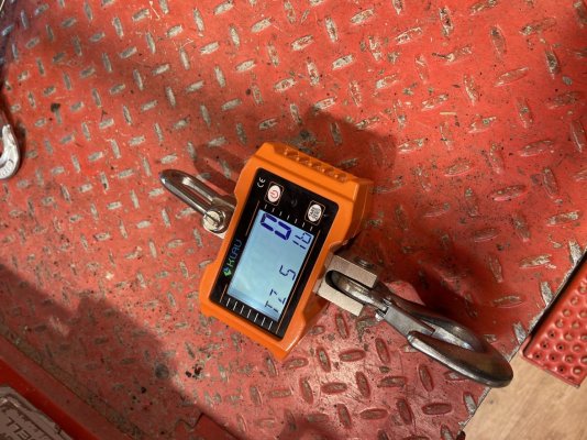
Fortitude- You’ve got the crane scale, I’ve got a KK42 that is all set up with the riggings and fish. Let’s get together and tie them together to get some real world numbers. If you remember we met over at Port Ludlow in Sept.
Rob & Anne
“Lady Anne” KK42
La Conner, WA
It's totally relevant in order to get a baseline to confirm/correct old assumptions about the amount of force created by the lift and drag a fish creates underway (in ideal conditions). From that baseline more models can be created to account for max loads, breaking strengths, loads on the rigging, etc.
PS - love it when we see Delfin around the Salish Sea. I feel like we're always one day behind you in anchorages. Hope to meet you in person one of these days.
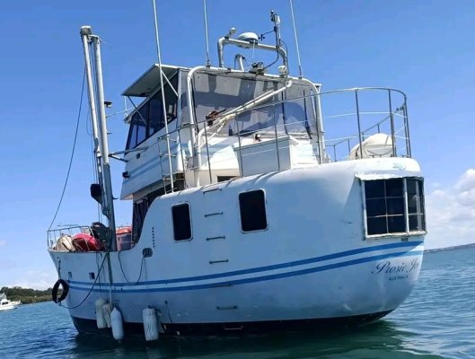
Cool boat. The poles look to be about mid waterline?
Probably about midships, almost all west coast of North America fishing boats have the stabilizer poles set well forward. Which reminds me about another load on the system; with poles forward the fish will damp out a bit of the pitching motion as well.
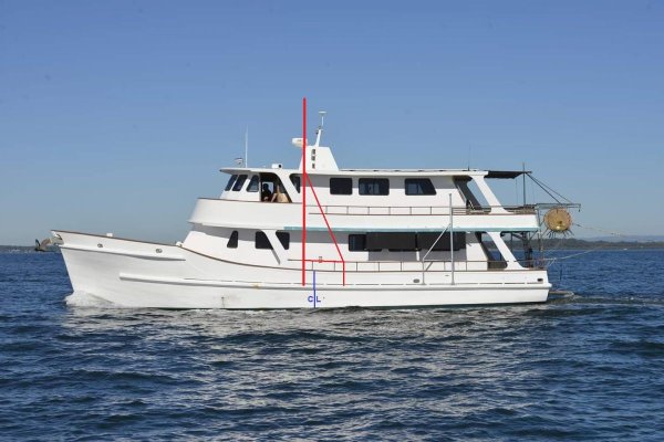
Red being proposed arms done in full 6m length of 80mm x 6mm ally tube.
Simi, I also built my 6 metre flopper-stopper out-riggers out of 80 mm diameter aluminum tubing but mine were only 2mm thick as I didn't want them to be heavier than needed.
I agreeI used an on-line calculator for columns under buckling forces which showed that the diameter has a much greater impact than thickness on the compression forces that a tube can handle.
That was the direction I was aiming forWhen deployed, you may want to aim for the outrigger to be level with the roof of your upper cabin so the forces on the roof are horizontal.
.You can attach a chain plate to the underside of the roof to avoid having to re-position the solar panels
That's interesting and valuable.
So that 780 is the case where you're dragging the fish sideways, essentially?
Solar panels are only an issue if going well aft of centreline.
Not as much structural support - lack of bulkheads- would be more of an issue.
When deployed, you may want to aim for the outrigger to be level with the roof of your upper cabin so the forces on the roof are horizontal. You can attach a chain plate to the underside of the roof to avoid having to re-position the solar panels.