sbman
Guru
- Joined
- Jul 25, 2017
- Messages
- 828
- Location
- USA
- Vessel Name
- Second Chance
- Vessel Make
- 42' Uniflite Double Cabin
Resealing the Capilano Helm pump - Step by Step Part 3
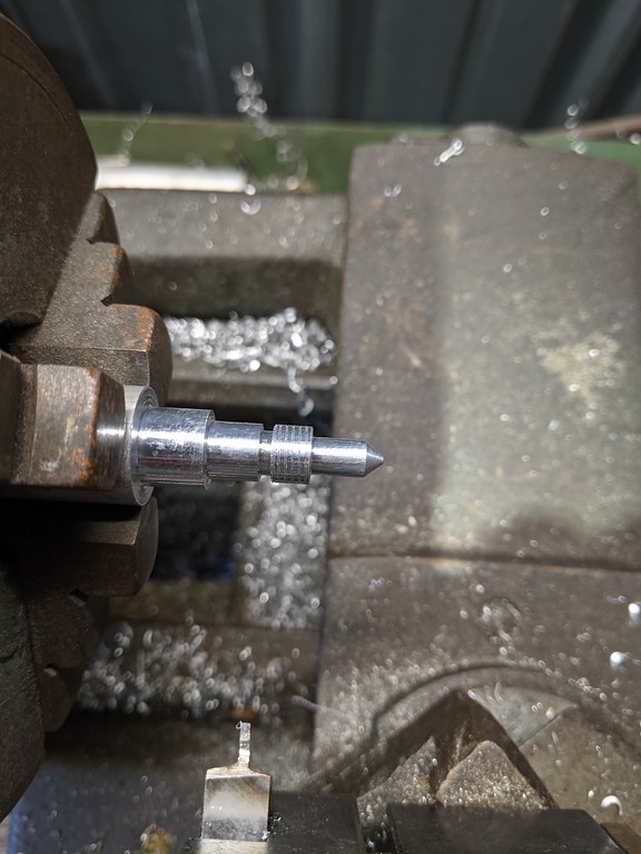
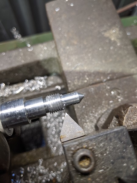
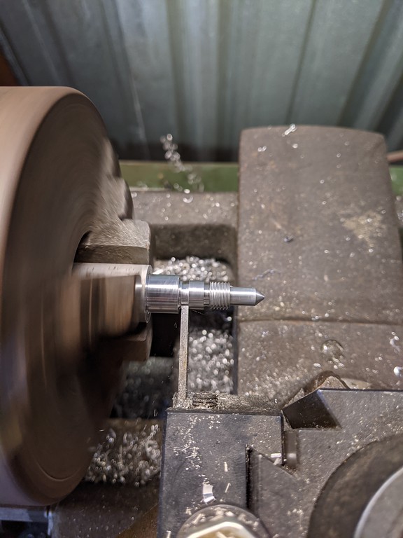
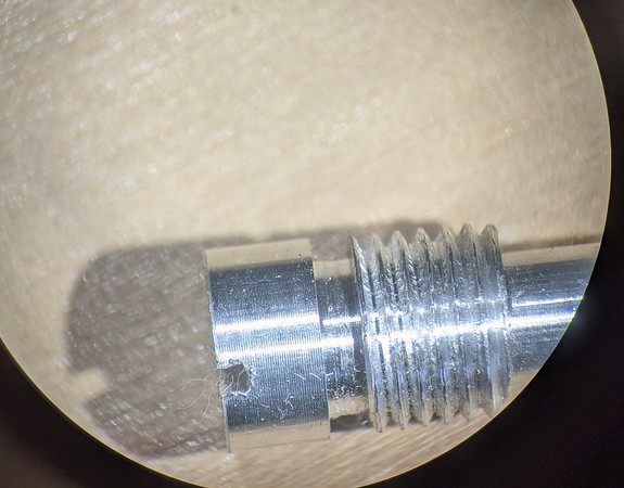
Step 9 - Change adjuster screw o-ring
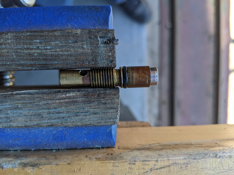
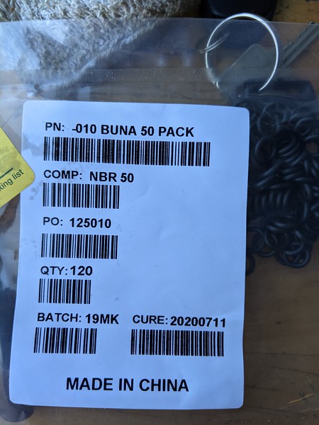
Now you can carefullly pry the o-ring off the adjuster with a pick and then slide the new one on, lubricate it with power steering fluid or sil glide. It uses a size 010, and I also chose the soft version for this.
Step 10 - Reinstall adjuster screw
Screw the adjuster into the back of the front cover by hand. The new o-ring should not cause any binding, if it does, double check that it's seated properly, well lubricated and not damaged before re-installing.
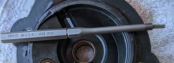
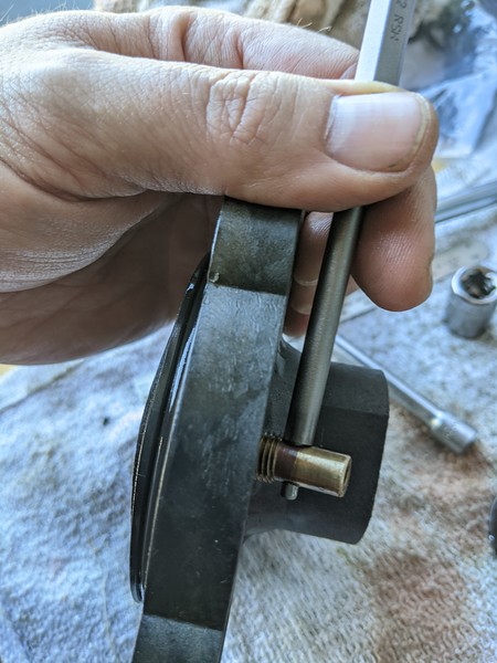
Now you need to install the roll pin. A roll pin installation punch is very helpful. Place the pin in the punch, line it up with the hole and then gently tap it into place. You can put the shaft back on the socket or any hard surface to install it.
Now the cover is ready to re-install.
Step 11 - Install front cover
To start, you need the swash assembly. It's the round bearing that has two half round lumps that seat in the front cover, and is sitting on top of the plungers on the main shaft.
Lift it off, and place it into the front cover.
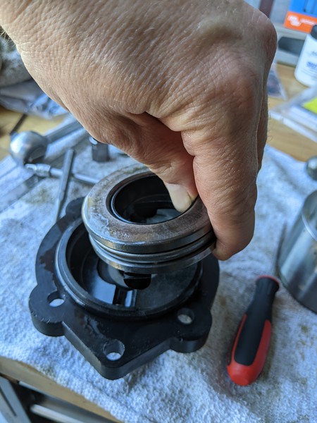
Be careful because the bearing is multiple pieces, so hold them together as you move it around. Do not pick up the shaft, the plungers have springs and ball bearings behind them and you don't want to lose any of those!
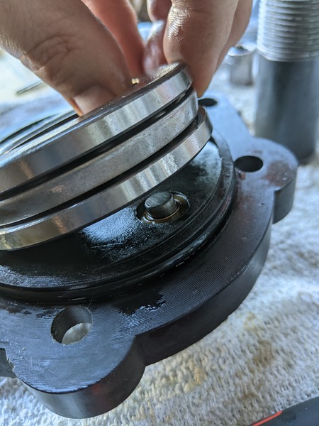
Line the bearing up so that the lumps ride in the valleys in the front cover on one side and on the adjuster on the other side.
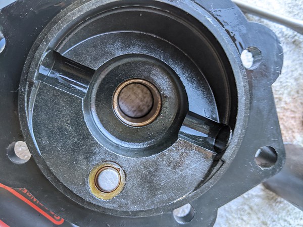
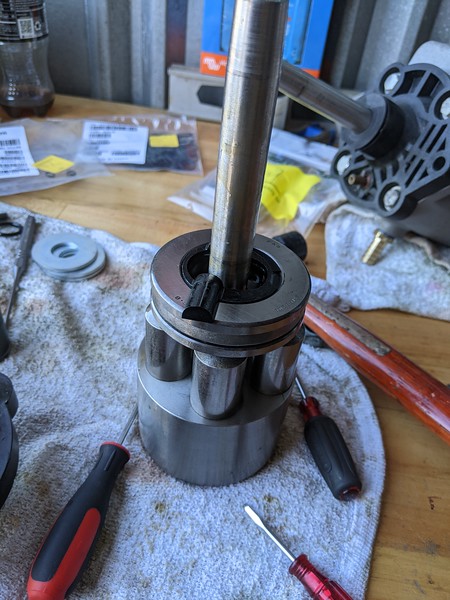
Now hold the bearing onto the front cover and slide it onto the main shaft. It should look like this:
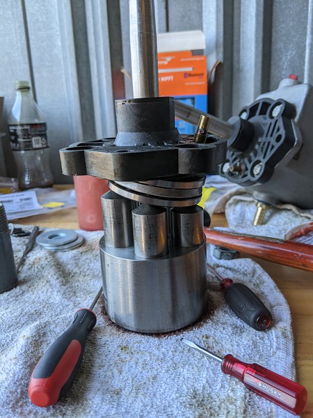
Step 12 - Reinstall shaft and cover in pump body
Place your spacers back on the shaft. You'll find they are too long. Push down on the front cover and spacers to compress the springs in the plungers. This doesn't take a lot of force, but get it down far enough to put the washer back on the hold it all together.
When you press down on the cover and spacers to get the nut off, a lot of power steering fluid will likely get pushed out of the pump onto the bench. It's a bit messy.
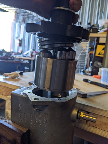
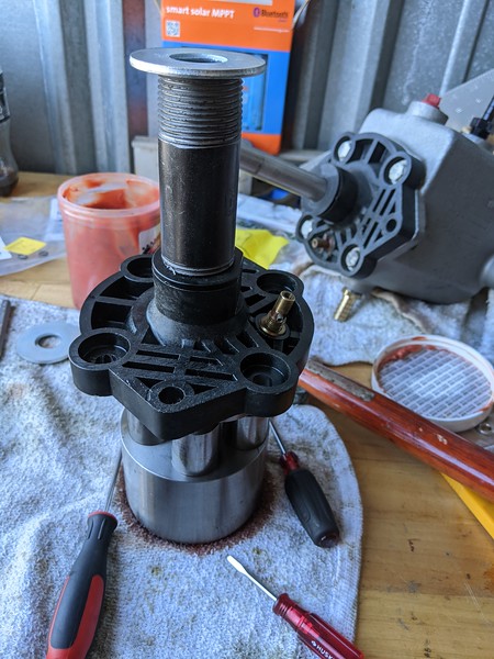
Now slide the entire assembly back into the pump body. You'll need to align the shaft with the pump body internally as you insert it, it has to be aligned with the machined surface in there to slide on freely. Do not use force, you don't want to damage the pump body or shaft. It should slide easily in 90% of the way. After that the large face sealing o-ring is touching the pump body and it gets a lot harder. Press it down into the body to engage the o-ring. Re-install the four 1/2" bolts and tap the key way back onto the shaft.
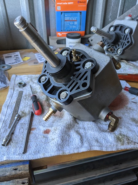
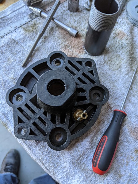
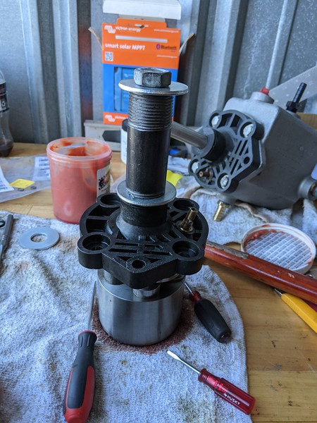
Make sure the adjuster is oriented towards the BOTTOM of the pump. Don't do it like I did in this picture and install it upside down. If you do install it upside down, just put the spacers and nut back on and unbolt it, rotate it to the correct orientation and then bolt it back up. All done!
Step 9 - Change adjuster screw o-ring
Now you can carefullly pry the o-ring off the adjuster with a pick and then slide the new one on, lubricate it with power steering fluid or sil glide. It uses a size 010, and I also chose the soft version for this.
Step 10 - Reinstall adjuster screw
Screw the adjuster into the back of the front cover by hand. The new o-ring should not cause any binding, if it does, double check that it's seated properly, well lubricated and not damaged before re-installing.
Now you need to install the roll pin. A roll pin installation punch is very helpful. Place the pin in the punch, line it up with the hole and then gently tap it into place. You can put the shaft back on the socket or any hard surface to install it.
Now the cover is ready to re-install.
Step 11 - Install front cover
To start, you need the swash assembly. It's the round bearing that has two half round lumps that seat in the front cover, and is sitting on top of the plungers on the main shaft.
Lift it off, and place it into the front cover.
Be careful because the bearing is multiple pieces, so hold them together as you move it around. Do not pick up the shaft, the plungers have springs and ball bearings behind them and you don't want to lose any of those!
Line the bearing up so that the lumps ride in the valleys in the front cover on one side and on the adjuster on the other side.
Now hold the bearing onto the front cover and slide it onto the main shaft. It should look like this:
Step 12 - Reinstall shaft and cover in pump body
Place your spacers back on the shaft. You'll find they are too long. Push down on the front cover and spacers to compress the springs in the plungers. This doesn't take a lot of force, but get it down far enough to put the washer back on the hold it all together.
When you press down on the cover and spacers to get the nut off, a lot of power steering fluid will likely get pushed out of the pump onto the bench. It's a bit messy.
Now slide the entire assembly back into the pump body. You'll need to align the shaft with the pump body internally as you insert it, it has to be aligned with the machined surface in there to slide on freely. Do not use force, you don't want to damage the pump body or shaft. It should slide easily in 90% of the way. After that the large face sealing o-ring is touching the pump body and it gets a lot harder. Press it down into the body to engage the o-ring. Re-install the four 1/2" bolts and tap the key way back onto the shaft.
Make sure the adjuster is oriented towards the BOTTOM of the pump. Don't do it like I did in this picture and install it upside down. If you do install it upside down, just put the spacers and nut back on and unbolt it, rotate it to the correct orientation and then bolt it back up. All done!
Last edited: