Waeco CR-110 Fridge Not Working

The friendliest place on the web for anyone who enjoys boating.
If you have answers, please help by responding to the unanswered posts.

Aussie Mike

Member
Joined
Nov 15, 2018
Messages
22
Location
Australia
Vessel Name
ShipShape
Vessel Make
Clipper 30
Hi All

I have a Waeco CR-110 fridge running off a 220amp AGM Battery. It usually draws around 4 to 5amps per hour and pretty much runs continuously.

While at the marina or under engine power, the fridge stays nice and cool (it won't run off 240V for some reason at the marina so still operated from the 12V battery, however, the boat is always connected to shore power via a Sterling Battery Charger system.

Recently the fridge has not been keeping cold at anchor. I'm getting a single red LED flashing every 5 secs inside the fridge next to the green power LED. Someone suggested a power issue so I installed a new 220amp AGM battery but it's still doing the same. Our BEP meter shows the battery operating between 13.2V to 13.8V and no current (5amps) is being drawn from the battery to operate the fridge.

All I can hear is the fridge fan running for about 2 mins then cuts off, the compressor then seems to hum for about 2 secs and stops and the fan starts again. That cycle is repeated over and over.

I have now been advised that the cable may be too small or faulty. If so, why is it running fine under engine power or at the marina?

My skills in this area are limited but just looking for some advice before calling the electrician. Any assistance is most welcome.

Cheers
Mike
 
Easy to check if the wiring is too small, several ways to determine it. One way is to put a volt meter on the leads at the refer and measure the voltage when it is trying to cool. The other way is to see what size wire is going to the refer and measure the distance along the wires. Check a table and see what size wire is called for given the distance and current draw. However if it used to work ok with the current size wire the wire is probably ok. More likely a fault with the refer control board or compressor. It shouldn’t need to run continuously when it is working though. Maybe needs more ventilation in the cabinet so the heat can get out and the compressor won’t work as hard. I would look first at the refer as the problem. Another way to check it would be to wire your new battery directly to the refer and see what happens, make sure to put a fuse inline just in case.
 
Ah, I feel your pain!

I have a couple of 110's. They do seem to be very voltage sensitive. They were also working fine in marina's and when the engines were running. I concluded that under those circumstances they were seeing a bit higher voltage than when i was at anchor. At the time my house bank was getting old and I suspected that voltage was too low. I have replaced the house bank but have not used the 110's since then, so don't know whether that fixed the problem or not. On sunny days my solar will bump the voltage up also, and I'm sure that helps.

At one point I found the earth wire in one of the fridges was loose. I'd suggest you remove the access panels to check for loose wires and while you are at it measure the voltage at those fridge terminals. It might not be the same as your BEP, and that might help determine if the wire run has too great a voltage drop on it or a poor connection somewhere.
 
Thanks for your reply.
Just to help eliminate the various causes, the fridge is well vented at the bottom, top, and rear by the way of exterior air vents.
 
Presuming your have a Danfoss/Secop BD compressor (most likely), then 5 flashes means "compressor overload."

Now, on the one hand, 5 flashes is supposed to be a serious problem (like "send it in,"), BUT there are a couple of things I would do or check first. I've seen it listed as "Thermal cutout of control module" or "compressor overload."

First of all, even though 5 flashes apparently doesn't relate to voltage drop (some of the other codes do), I would do some checking on what you have. Either check the voltage at the compressor control (if it will start at all?). Or, if you come back and tell us the sum total of your wires size and length, all the way to the battery, we can figure it out. (So like, 20' of 8AWG, then 2' of 6 AWG, then 1' of 2/0) or whatever. This probably isn't the main problem but is important to the control module.

A related important thing is to not have it on a circuit where another load can interfere. Of course they say run it right to the battery, but we know if we did that every time someone asked, our batteries would have 50 wires on them. But the concept is still to run it to someplace where it is king, not on a circuit where other loads can interfere.

Third, if yours runs almost continuously, it may be running pretty warm. With the BD 35 or 50, you can add a second fan on terminals + and F, and that fan will come on whenever the compressor is running. It has to be under .5 amp, but that is easy to do nowadays. I like the Noctua NF-F12 x 25 for free air, and the NF-A version for if it's pulling through a condensor radiator.

Above said, if yours is a "cooler style," then this may not be so easy. It's easier on a built-in style.

I'm on my way out the door, so have to run, but I do have some .pdf's I could upload later. Or, seek out Penguin UK's videos or documentation, which are excellent.

If I get back and someone more knowledgeable hasn't figured out the issue yet, then I'll post some documents if you'd like.

PS: On the 220v not working. Apparently some of the older (not sure how old) dual voltage controllers had a weakness in this area (same for the 110v ones). When it fails you can still run on 12 volts. You can replace these controllers with a new one (one screw and a wiring connector) - they are around $300 US but do have some improvements so at least you get that.

Please excuse any rushing mistakes.
 
Sounds like Frosty is pretty good with these. Good resource.
 
One thing to add if you do get it running again. The BD 35 and 50 (yours could be either but my 130 is a BD35; buddy's 150 is a BD50 so I'm guessing you have a BD 35), are able to run at varying RPM's. That is controlled by a simple resistor. The options are 2,000 - 3,500 RPM's.

(Note some fancier refrigerators with digital controls may have a variable speed type control such as Coastal's Merlin; but I'm speaking of the more pedestrian ones that use a resistor to set the speed at one setting. If you have variable control then this does not apply.)

When you buy a fridge, they have "decided" on some best RPM and that's what you get as stock. For example my 130 was set to run at 3,000 RPM. So fairly high. Now this may be necessary in a hot place, or if I dumped tons of warm stuff in on Friday night all at once, but I run mine steadily.

They say if you can keep it to around 50% duty cycle (or maybe a bit more IMO) then that's good. BUT, the lower the RPM the better. Easier on the compressor, more efficient, and quieter. So I adjusted mine to the lowest RPM (2,000) and it's running happily at about 35% duty cycle. Great.

But if you are running at nearly 100% duty cycle? Then I think I would want to try it at the maximum RPM to see if that would help.

One could buy other resistors, or companies like Coastal Refrigeration make an adjustable board (so you can choose any of them). What I did was remove the resistor and make up a simple Y harness with the original resistor and a switch. Switch one way is no resistor; switch the other way is the original one. I figure I may want to use that original 3,000 RPM in hot weather.

Here are the values that Vitrifrigo, for example, sell as possible originals (for the BD 35 or BD 50)

R101023.1
Resistor card, NEW,1523 Ohms, C55BT/C110BT/C65 - Yellow dot (3500rpm)

R101022.1
Resistor card, NEW, 692 Ohms C30BT/C130/DP2600 - Black dot (3000rpm)

R101021.1
Resistor card, NEW, 277 Ohms C51/C60/C62/C85/C115 - Red dot (2500rpm)

These are little "cards" that plug on to the quick connects on the compressor control module, but you don't have to use those (or you could). I imagine you could also use any value in between.

It would be interesting to know which one you have now. If it's set at a lower RPM, you could gain some "power" to the unit's cooling capabilities by running it at a higher RPM. My 130 liter upright style came with the black dot so was running at 3,000 RPM. Much higher than necessary at my typical temps (say up to 80ºF). I imagine your climate is hotter though! (also I added a couple of inches of insulation board on the outside on all sides but the door).

PS: If you do take a peek "under the hood" the compressor control (black box the wires all attach to) will have a part number up above where the AC wires go in. Something like 101N0150. You might note that.

If you feel like it, post up a pic of the front of the control.
 
Last edited:
Thanks for your detailed response Frosty

Here are some images of the fridge.
https://photos.app.goo.gl/E321EjC2W4bJPnAQ7
Plenty of ventilation on the exterior.
Some shots of the fan and compressor

Your reply mentioned 5 red flashes.
My post said one red flash every 5 secs.
This may have led you down the wrong path in regards to the fault.

Mike
 
Hi Mike,

In the photo some of the cooling fins look pretty rusty? Maybe its just the light in photo and there is in fact no rust at all, but if not, then maybe the gas is lost...

I realise you are hoping to fix/repair without a technician, but in case you (unfortunately) need to go that route I have had good luck with this guy for all refrigeration stuff (name is Gary) from down your way on the GC:

iMarine Airconditioning

Hamish.
 
Lots of things to check.
I will suggest that while doing the voltage check at the fridge terminal while it is running you also need to check the actual voltage at the battery while the fridge is running. It is the difference , or voltage drop, you are looking for.
Note the battery voltage, the fridge voltage and then you can calculate the Vdrop.
Then the wire size can be checked for sizing. Just checking at the fridge may not tell what you need.

Check for loose connections. I went through this last year with our small chest freezer.
Erratic operation, light on but no cigar periodically. I finally figured out it was a poor connection.
Enough current getting through to light up the control board but not enough to actually run the compressor or keep it running when it did startup.
. Mine was a poor plug/socket, my fault. I was not being cheap but chose the wrong type.

I have seen fuse holders do this also. If the clips that hold the fuse are loose or weak the fuse may become part of the problem. If lucky the looseness MAY heat the fuse enough to blow but not always.

Put a portable wireless thermometer in the fridge compartment to monitor the actual temp. in the cavity. DO not assume that natural ventilation is adequate. They are about $20-$30 for one with a remote sensor which you will need. Put the remote in the cavity near the top.
Monitor it through several cycles. I have had this discussion with more than a few people. Often a small computer type fan is needed to FORCE enough air movement to adequately carry off the heat the compressor is trying to get rid of.

I agree that Frosty has a good point about the adjustments of the motor speed by the resistors. The basics need to be done first before going down that road.
 
Mike
I am going to be very interested in how this pans out for you.

But first, my 110's are the CF 110 chest-type fridge freezers. They are on my flybridge and only used as supplemental capacity, mostly for frozen stuff, on extended trips when they can stay at -10°C but run a lot. They have much, much shorter duty cycle time when just running as fridges. Both are dual voltage, but the AC is 110V so I don't use it. One was already old and quite rusty when I bought the boat in 2012. I bought a new one in 2013 before shipping the boat back to Australia.

I did have issues with the old one. The best place for parts if any are needed is a shop in Broome, link to website below. I replaced a circuit board.
https://www.allvolts.com.au/FRIDGE-FREEZER-COOLER-WAECO.html

I've changed out from cigarette light plugs/sockets, but I think it made no significant difference. I have never asked the guys in Broome about the low voltage issue, but it just might be worth contacting them to check if they have cone across it and know a solution. From the reviews (see link) it seems to be a common issue. I'd love to know if there is some voltage boost trick/gadget that can be added.
https://www.productreview.com.au/listings/waeco-cf-110ac

Because, as you have found, at marina's or with main engines running these fridges work fine.


I ran some tests on power used at one point, whilst at the marina on shore power (batteries on float charge)

The old one used 21Ah over 24hrs to hold at 3°C. ie fridge function. But to go from "off" & pull down to -5°C it used 252Ah over the 24hr period. It would go down to -10°C when set on 6 or 7 (running virtually continuous on 7)

The new one has a digital temp setting (instead of the old 7 step lights) and is better performed. It would set and hold -5°C or -10°C over 24 hrs for 62 Ah or 131 Ah respectively.

On my trip when I used them a lot at anchor, with the old house bank and even with solar boosting voltage during the day they would struggle to stay below 0°C.

PS Having written all that, and having read posts above I realise that I have never checked the actual voltage drop from the pilothouse circuit panel to the flybridge outlets or fridge terminals themselves. I also need to check wire gauge..... I'm now thinking its too small.....
 
Last edited:
Thanks for your detailed response Frosty
Here are some images of the fridge.

Thank you! It's good to see it. Some general info here, but skip down to just below the line of asterisks for the stuff about the problem.

So you and I both have the same controller unit, the 101N0500. I don't know when that one first came out, but my refrigerator is 2015 vintage and has it. Another friend has the same exact fridge as me but 2020 vintage, and it has the newer 101N0510 (with which you can use certain electronic thermostats; otherwise I think it's similar).

So anyway, yours is not an ancient one and looks familiar to me.

The two red flag terminals at the very top are your incoming AC wires (110/220).

Then there is a break and then a bunch of terminals down below. The top ones are the DC + and DC - that are bringing in the power (apparently with a voltage issue at the moment, which these control boxes are very sensitive to).

Next down, F, is the negative lead for the fan that comes on the compressor, and the positive is above on one of the + terminals (skinny wires).

Next down, I believe A and C are for the light in the fridge.

Next down, D is where your flashing diagnostic light hooks up (the other lead goes to the + terminal)

Next, C and T are where the thermostat hooks up (the resistor is on T typically although I don't see it or Waeco may have put it somewhere else on the same line. OR, if there isn't one, your fridge may always be running at the lowest RPM - maybe not best in your climate).

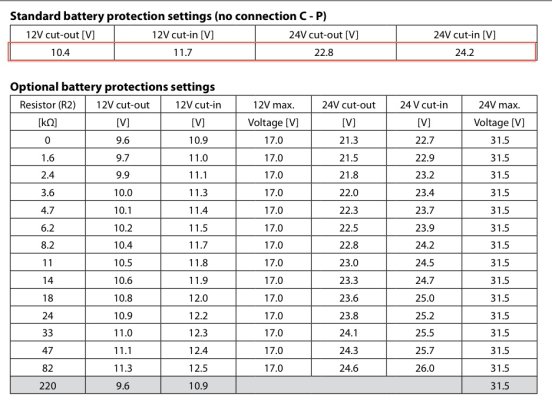
P I think used to have a resistor that had something to do with low voltage battery protect cutout, but a fellow at Secop (Danfoss) told me that is now built in somehow so you may not see anything there.

One difference between yours and mine is that you have the style with the "fence" of condenser coils wrapping around whereas mine has a small "radiator" the same size as the fan. So just two ways of doing the same thing. Then the black "ball" is the actual compressor.

Side note is that I can't tell if this is the case or not, but as important as good insulation, is trying to set it up so that the warm air the fan sends out, cannot then be sucked in again by the fan (vicious cycle of hot air). I can't really tell how yours fares that way. The style of mine is more one long line vs. a wraparound, so it was not too hard for me to make some septums so nary the twain shall meet.

In case you were wondering :flowers:

But on to the problem:
**************************************************************************************
**************************************************************************************
Your reply mentioned 5 red flashes.
My post said one red flash every 5 secs.
This may have led you down the wrong path in regards to the fault.

Thank you for pointing that out! Geez, that'll teach me to rush. :facepalm:

The good news is one flash is probably much less dire than five, and more fixable by you. Yay. As mentioned above these electronic control units are super sensitive about voltage (or you could say, about avoiding voltage drop).

So what they say for one flash is "low voltage reaching the compressor."

Here are Penguin's steps:

1 Flash Low Voltage

There is insufficient voltage reaching the fridge compressor.

a) Confirm the wire dimension is correct

If this is a new installation check the wire sizing [added by me: you can check the sizes and lengths as mentioned in previous post. The basic guideline is 8AWG max 20 meters; 10AWG max 12 meters; 12 AWG 8 meters.

This also assumes good connections, clean power (nothing else that's going to affect it on same circuit), etc.]

b) Test the Power supply
To properly test the power supply to a Danfoss powered 12v or 24v system, the following testing procedure must be carried out. This will establish whether the power supply feeding the system is free of bad, loose and/or high-resistance connections.
Reading the voltage on the panel or at the batteries is meaningless, as is the fact of a new installation or new batteries. Size and the capacity of the battery bank is irrelevant.
1. Turn off the breaker (or remove the fuse) supplying DC power to the system. 2. Unplug one of the thermostat leads at the controller. 3. Using a multi-meter, read the DC voltage at the battery terminal(s). 4. Connect the multi-meter reading DC voltage to the power terminals (+ and -)
on the controller so that it can be left connected and monitored. 5. Turn on the breaker (or install the fuse) to the system. 6. Check that the voltage is the same as the voltage seen at the battery
terminals. 7. Whilst watching the multi-meter, reconnect the thermostat lead and monitor
the voltage continuously before, during, and after the compressor starts or attempts to start.

Interpreting power supply results

If the power supply is free of loose, bad, and/or high resistance connections, the voltage reading at 5 above will stay very stable and only drop slightly when the compressor starts. As a general rule, on a 12v system the reading should not drop below 12v. If, when the compressor attempts to start, the voltage reading drops significantly, a bad electrical connection should be suspected. If the voltage drop is sufficient to fall below the 10.5v (23v) cut-off built in to the controller, the compressor will stop. (At this point the voltage may return to it s original reading.) The fan or pump will continue to run for approx. 45 seconds and then the compressor will attempt a re-start. If the voltage is then above 11.5v (23.5v) the compressor will start or attempt to re-start again.
WARNING If the multi-meter being used is a digital model that is slow to react, the voltage may drop below 10.5v (23v) and then recover too quickly to register on the meter. This can lead to the situation where the compressor starts then stops from low voltage, the voltage returns to its original value, and there being no significant drop on the meter.
If the compressor starts and runs OK but stops after a short while, the voltage may be gradually dropping towards and below the 10.5v (23v) cut-off point. This should be easily identified on the meter. If the nature of the fault is such that the voltage reading at 5 above drops below 10.5v (23v) even before the compressor attempts to start, a very bad electrical connection must be suspected. This is because even the small load of the fan or pump relay, both less than 0.5 amp (0.25 amp), is seemingly sufficient to reduce the voltage considerably.
What to look for A loose and/or high-resistance connection can be anywhere in the supply between the batteries and the controller. i.e. a bad breaker or fuse, a loose or corroded screw connection, a poorly made or corroded crimp connection, a damaged section of wire, etc.

HINT
A good place to look first is the negative (ground) connection, especially on a European-built boat. These tend to be multiple, common connections that are added to over time.[/quote]

End of Penguin's one-flash advice.

Richard Kollman (another refrigeration pro) adds this about the one flash; as above it is a concern about a voltmeter being used:

• One LED flash and a 4 second pause indicates a boat wiring electrical resistance problem or low batteries. Because of modules sensitive to milliseconds of a voltage spike they cannot be detected by a voltmeter. Solution is to bypass boat’s wiring till problem is located point of electrical resistance.

So that's another way to check it if you have extra cabling: Just hook it up directly with new wire, even if it just runs across the furniture for the test :)
I have a couple of other documents from other refrigeration sources, but they say basically the same thing. One flash is pretty straightforward.

I'm no expert, but I also can't tell where you are on the scale of knowledge. So if anything about checking it out sounds confusing, say something and maybe I (or someone else here) can explain it in more detail.
 
Last edited:
Well Frosty, for someone who presents themselves as "no expect" you certainly know quite a bit, far more than myself. My electrical skills are very limited but I'm happy to have a crack.


Okay, so I have read everything that has been written and while some of it goes over my head I have made the following observations. It seems to be a voltage problem at anchor. I say that because under power or at the marina (on 12V) the fridge operates flawlessly.


That is what is bothering me, if it's a wiring issue, then wouldn't it also be an issue under power or at the marina? The wiring doesn't look to me more than 3 or 4mm.


I'll follow your instructions and check the voltage to the DC + & - connections on the fridge to evaluate the current draw. If there is a drop then the recommendation is to up the cable to 6 or 8mm, is that correct?


Have I missed anything?


Cheers
Mike
 
That's a good clue: Works fine at marina (on 12v); has issue at anchor.

That makes me think even more that it is a voltage (drop) issue. Here is why:

1) So at the marina, unless your boat is unusual, your 12v system is fat and happy? Why? Well most larger boats have a battery charger (or inverter/charger) that runs off of shore power. So that's keeping the 12v house bank nice and plumped up in the voltage dept. Many chargers float at 13.x volts.

2) Now at anchor you are running on 12v batteries only*. No charger crutch. If you have lead acid batteries (flooded, AGM, gel), then they are probably at maximum voltage of 12.8 (or less) once you are not charging*. And it only goes down hill from there. You could be at 12.2 or so by morning (or any time you are not charging; I say morning because I am used to solar, so when the sun comes up...).

Now let's say you have a bit of voltage drop in your wiring. Just for an example, we'll say you have 25' of 10AWG wiring. And maybe your refrigerator does not have it's own powerpost or breaker right near the batteries, but instead has to share a breaker with some other load (I'm not actually quantifying that here, but it's another "straw").

So that would be 2.8% voltage drop (I'm not counting other competing loads, or the other wire runs that may be larger as you get closer to the batteries).

On shorepower, when you are at 13.3 volts (or so), that 2.8% voltage drop takes it down to 12.9 volts. Nice and happy.

At anchor, if your bank gets down to 12.2 volts, then the 2.8% voltage drop takes it to 11.85 volts. Hmmm, not so good. These compressors will not want to start up at that voltage.

One more factor: These compressors can have a "battery protect" setting. Meaning they will stop working below X voltage (even before they would starve on their own). On my portable Dometic cooler style refrigerator (BD 35 with some added features put on by Dometic), there are three settings. IIRC, the highest one is up around 12 volts or a bit over.

On my Vitrifrigo (refrigerator with same controller as yours), it's supposedly built in, and I think it can be changed but I'll have to have a look at the manual. It can also be controlled by a resistor on the P terminal (I can't see if you have one there or not). But in any case, these controllers don't like low voltage, so battery protection aside, it's good to keep them happy for their own sake.

So I would focus first on your wiring. But why has it worked up until now? Maybe your batteries were in just a touch better condition, or a connection has gotten slightly corroded or loose. In any case you can't possibly go wrong by feeding the refrigerator with the least possible voltage drop. 12 volts, bring in the tree-trunk sized wiring! No, just kidding, but I would trace the path starting at the batteries. Where does the refrigerator wiring circuit come in? Is it close to the batts? Does it share a breaker with other loads (especially if they are demanding)? How long is the run to the compressor controller? What gauge wire is it? If you report back with that, we can do some calcs and make some suggestions.

If all that is up to snuff, it's possible your batteries are getting just enough more tired (I don't know your bank though).

*Asterisks above are because I don't know what sort of charging you may or may not be doing at anchor. If you are running a generator, then if my theory is correct you would NOT have any problem with the refrigerator while charging, or shortly thereafter. But later the battery voltage would sink and then....

Same if you have solar. All should be good during the day while the sun's out, but then later...

So does any of this sound right? In other words, you are charging at the dock but not at anchor (or at least at anchor the refrigerator works while you are charging but not later)?

I had a buddy who while we were putting in a new "main" refrigerator was running one of the Dometic portables (same compressor) in the interim. He had about 25' of 10 AWG on a temporary wiring scheme. Sure enough, when his batteries sagged in the middle of the night.... fridge error code and it would not run. Since it was temporary he shortened the wire (now it went across the room, definitely temporary) and all was fine.

One side note: This is one reason "lithium" batteries are popular. Instead of the voltage sagging as they go, it pretty much stays up right to the end. That's not to say they are the best choice for everyone (not right now anyway), but that is one of their star features.

One more side note: Reason I used 5 amps in the voltage drop calc above is that even though the refrigerator runs on about 2.5-4 amps (depending on RPM), I believe there is a start up current that is higher. Maybe around 6 amps or so.

Frosty
 
Hi Frosty

1) So at the marina, unless your boat is unusual, your 12v system is fat and happy? Why? Well most larger boats have a battery charger (or inverter/charger) that runs off of shore power. So that's keeping the 12v house bank nice and plumped up in the voltage dept. Many chargers float at 13.x volts.

The boat is equipped with a Sterling Pro Charge Ultra.

2) Now at anchor you are running on 12v batteries only*. No charger crutch. If you have lead acid batteries (flooded, AGM, gel), then they are probably at maximum voltage of 12.8 (or less) once you are not charging*. And it only goes down hill from there. You could be at 12.2 or so by morning (or any time you are not charging; I say morning because I am used to solar, so when the sun comes up...).

I recently purchased a new house battery AMP TECH 220AMP AGM in the hope that it was the issue. Usually operates between 12.8V and 13.2V at anchor.

Now let's say you have a bit of voltage drop in your wiring. Just for an example, we'll say you have 25' of 10AWG wiring. And maybe your refrigerator does not have it's own powerpost or breaker right near the batteries, but instead has to share a breaker with some other load (I'm not actually quantifying that here, but it's another "straw").

So that would be 2.8% voltage drop (I'm not counting other competing loads, or the other wire runs that may be larger as you get closer to the batteries).

On shorepower, when you are at 13.3 volts (or so), that 2.8% voltage drop takes it down to 12.9 volts. Nice and happy.

At anchor, if your bank gets down to 12.2 volts, then the 2.8% voltage drop takes it to 11.85 volts. Hmmm, not so good. These compressors will not want to start up at that voltage.

One more factor: These compressors can have a "battery protect" setting. Meaning they will stop working below X voltage (even before they would starve on their own). On my portable Dometic cooler style refrigerator (BD 35 with some added features put on by Dometic), there are three settings. IIRC, the highest one is up around 12 volts or a bit over.

On my Vitrifrigo (refrigerator with same controller as yours), it's supposedly built in, and I think it can be changed but I'll have to have a look at the manual. It can also be controlled by a resistor on the P terminal (I can't see if you have one there or not). But in any case, these controllers don't like low voltage, so battery protection aside, it's good to keep them happy for their own sake.

So I would focus first on your wiring. But why has it worked up until now? Maybe your batteries were in just a touch better condition, or a connection has gotten slightly corroded or loose. In any case you can't possibly go wrong by feeding the refrigerator with the least possible voltage drop. 12 volts, bring in the tree-trunk sized wiring! No, just kidding, but I would trace the path starting at the batteries. Where does the refrigerator wiring circuit come in? Is it close to the batts? Does it share a breaker with other loads (especially if they are demanding)? How long is the run to the compressor controller? What gauge wire is it? If you report back with that, we can do some calcs and make some suggestions.

As mentioned earlier the battery is brand new and is located about 5 feet from the fridge. I think the battery shares power with a bilge pump. I will investgate the wiring and replace it with some 6mm or 8mm wire.

If all that is up to snuff, it's possible your batteries are getting just enough more tired (I don't know your bank though).

*Asterisks above are because I don't know what sort of charging you may or may not be doing at anchor. If you are running a generator, then if my theory is correct you would NOT have any problem with the refrigerator while charging, or shortly thereafter. But later the battery voltage would sink and then....

Same if you have solar. All should be good during the day while the sun's out, but then later...

I do have solar (100amp panel that delivers around 5amps per hour)

So does any of this sound right? In other words, you are charging at the dock but not at anchor (or at least at anchor the refrigerator works while you are charging but not later)?

Correct

I had a buddy who while we were putting in a new "main" refrigerator was running one of the Dometic portables (same compressor) in the interim. He had about 25' of 10 AWG on a temporary wiring scheme. Sure enough, when his batteries sagged in the middle of the night.... fridge error code and it would not run. Since it was temporary he shortened the wire (now it went across the room, definitely temporary) and all was fine.

One side note: This is one reason "lithium" batteries are popular. Instead of the voltage sagging as they go, it pretty much stays up right to the end. That's not to say they are the best choice for everyone (not right now anyway), but that is one of their star features.

One more side note: Reason I used 5 amps in the voltage drop calc above is that even though the refrigerator runs on about 2.5-4 amps (depending on RPM), I believe there is a start up current that is higher. Maybe around 6 amps or so.

Many thanks Frosty, I will report back when I have been to the boat in a few days

Frosty
 
Hello Aussie Mike,

Thanks for writing back the details. I agree your battery sounds good, the wiring run sounds good (although I don't know exact lengths and cable sizes), etc.

But, for all that, I still think the problem has something to do with voltage (drop).

At the dock, your ProChargeUltra (I have one of those in an RV) will be supplying charging to the batteries, plus power for your loads. And if I'm understanding correctly, the refrigerator works fine at the dock on 12 volts (we know the 110/220 part of the module is on the fritz, but that is separate). So that kind of "proves" that nothing is "broken."

On anchor, not so much. That's when your boat electrical system is more-or-less on its own (100 watts of solar will contribute though, but not at night).

So, I still think it is one or a combination of these factors:

1) Wiring long and thin enough to cause some voltage drop.

2) Connection loose or dirty.

3) Other load on same circuit contributes to problem.

4) Since your battery bank is not huge, it could even be a load on a different circuit, if you have something that powers up with a bit of a "hard" start.

5) Batteries sag at times in the night but maybe you don't see it (may be really quick when compressor starts) resulting in, you guessed it, voltage drop.

One other thing I'm going to have a look at (but you could also check). Apparently connector P (second up from bottom) used to be used to tell the unit what to use as a low voltage cutout (this is still shown in the diagram). I don't have a resistor there (this is separate from the speed resistor which is on terminal T), so one time when I had Danfoss on the phone I asked about it (I had gotten a "good" guy so took advantage of that to ask a bunch of questions). IIRC he said that is now built in to the module.

Now, yours may have a resistor there (or in line with that terminal, since each refrigerator brand can tweak things on the compressor. If you see one I'd be interested.

I'm also going to go have a look at the compressor literature, because I think I remember reading something about how the value could be set with a program. But I think it also lists the default.

Not saying you even want to change it, because low voltage is not good for the control unit, but it would be nice to know if it's kind of "high" (like say over 12 volts).

******************
You also have the option at any time of replacing the module with the newer one (101N0510). This is the one that has the AC (110/220) option. There is also a DC only one. I had the choice of either when I bought my refrigerator and I went for the AC-added one and have found it to be handy a few times (like once I was working on my DC system and it was down for a few days and I was able to just separately run the refrigerator on AC). The module is easy to change, but it's not super cheap (about $285 US). You would get your AC function back (or the DC only module might be a bit cheaper). But my guess is it's not that.

Summary:

I still suspect it's a voltage drop problem. Not saying that's 100% for sure, but that's what I think. I'd be interested to hear more about exact wiring length, size, connections (just if you have checked them), etc. Sounds like you will come back with more info. Great, let's get it going again if we can!

I will have a look and see if I can figure out the default low votage cutout (unless you have a resistor in line with terminal P). I don't think that's the issue but still curious what it is (for myself as well).
 
Last edited:
EDITED TO ADD:

While the info in this post is correct, I think the following post has a better "nugget," so you might want to just skip to that one. Check out the bolded sections. You can always come back to this post when you are bored ;)

*****************************************
I just spent some bonding time with the manual (this is the Danfoss manual). Conveniently, I have the same module as you do (101N0500), so I already had that highlighted.

I took a close look at the voltage cut-out/cut-in info because I wasn't totally clear on what the fellow told me or how it worked.

So the module diagram (not shown here) shows a resistor between terminals C and P. Turns out that is optional, but with no resistor there (which is how mine is - no resistor there), there is a default set of values for cut-out/cut-in voltage. You can add a resistor there (again, this is different from the speed resistor on terminal T) to change the value.

The default setting is kind of middle of the road. The compressor will cut out if voltage goes below 10.4 (however this is not resting voltage but the drop induced when the compressor tries to start, I believe), and cut back in when the voltage rises to 11.7

I will add the chart to this post. I put a red outline on the default setting at the top.

(see below)

I believe on the newer unit (the 10N0510) these values can also be set by "tapping in" with a Windows computer. The 510 has joined the modern era ;) It will also accept things like Isotherm's ITC digital thermostat. If you've ever had one of the "cooler style" compressor boxes, they usually have this type of thermostat. I had one on a CF50 and it was a bit of a come-down to go back to the manual dial inside like we both have now.

But for us it's default or resistor for voltage cut-out/cut-in value setting.

I'm going to look at a few more documents I have saved about the low voltage "1 Flash" behavior and see if there is anything else to glean. I'll post if I find anything interesting.

Anyway. Here is the voltage cut-out/cut-in chart:
 

Attachments

  • Danfoss Secop 101N0500 voltage protection chart.jpg
    Danfoss Secop 101N0500 voltage protection chart.jpg
    182.2 KB · Views: 6
Last edited:
All I can hear is the fridge fan running for about 2 mins then cuts off, the compressor then seems to hum for about 2 secs and stops and the fan starts again. That cycle is repeated over and over.

Sorry if I'm posting too much info. Anyway.

I was doing a bit more reading about the 1-flash and diagnosis, just to see if anything would jump out at me. I think something has. If you want to "skip ahead," just compare your bolded quote just above with the bolded section below. I think we have a match.

I posted some Penguin instructions way up at the top of the thread, and several refrigerator troubleshooting documents repeat that. But here Coastal added a bit of their own verbiage above that same advice:

Power supply testing on Danfoss DC powered refrigeration systems

To properly test the power supply to a Danfoss powered 12v or 24v system, the following testing procedure must be carried out
[Note: This is the procedure I posted upthread a ways from Penguin]. This will establish whether the power supply feeding the system is free of bad, loose and/or high-resistance connections.

Reading the voltage on the panel or at the batteries is meaningless, as is the fact of a new installation or new batteries. Size and the capacity of the battery bank is irrelevant.

It kind of made me chuckle because of course they have heard people saying "But my battery bank is in great shape and the voltage is good (I'd probably say the same, so not dissing you at all :flowers:).

Anyway, next I read through the standard info again, and then at the bottom they had added "Interpreting results" (of the tests I mentioned yesterday). Look at what it says will happen if you get into a cut-out/cut-in "vicious cycle" due to low voltage (the part I emboldened). It kind of matches the part I emboldened in your quote at the top of this post. (This would be with the 1-Flash issue.)

Interpreting results

▪ If the power supply is free of loose, bad, and/or high resistance connections, the voltage reading at “5” above will stay very stable and only drop slightly when the compressor starts. As a general rule, on a 12v system the reading should not drop below 12v.

If, when the compressor attempts to start, the voltage reading drops significantly, a bad electrical connection should be suspected. If the voltage drop is sufficient to fall below the 10.5v (23v) cut-off built in to the controller, the compressor will stop. (At this point the voltage may return to it’s original reading.) The fan or pump will continue to run for approx. 45 seconds and then the compressor will attempt a re-start. If the voltage is then above 11.5v (23.5v) the compressor will start or attempt to re-start again.
WARNING If the multi-meter being used is a digital model that is slow to react, the voltage may drop below 10.5v (23v) and then recover too quickly to register on the meter. This can lead to the situation where the compressor starts then stops from low voltage, the voltage returns to it’s original value, and there being no significant drop on the meter.

▪ If the compressor starts and runs OK but stops after a short while, the voltage may be gradually dropping towards and below the 10.5v (23v) cut-off point. This should be easily identified on the meter.

▪ If the nature of the fault is such that the voltage reading at “5” above drops below 10.5v (23v) even before the compressor attempts to start, a very bad electrical connection must be suspected. This is because even the small load of the fan or pump relay, both less that 0.5 amp (0.25 amp), is seemingly sufficient to reduce the voltage considerably.


************************************

Additional info from same document. These possible issues would be in addition to the possibility of too-small wiring. But they would be more likely to "crop up" after awhile as connections age (have you always had the problem at anchor or is it new?).

What to look for

A loose and/or high-resistance connection can be anywhere in the supply between the batteries and the controller. i.e. a bad breaker or fuse, a loose or corroded screw connection, a poorly made or corroded crimp connection, a damaged section of wire, etc. HINT A good place to look first is the negative (ground) connection, especially on a European-built boat. These tend to be multiple, common connections that are added to over time.


Hope this helps and is not too much.

Frosty
 
Last edited:
Hi Frosty
It seems you have narrowed it down to one or two issues (well done) so I'll get myself to the boat and check them out. I'll probably just replace the wiring but will have to wait until we go out again to test your theories. Thanks for all your efforts, greatly appreciated. Thanks to everyone who contributed.
 
I'll probably just replace the wiring but will have to wait until we go out again to test your theories.

Sounds like a plan.

I'm not sure if you mean a temporary testing replacement, or a permanent one. If it's a permanent one, and you measure the distance (using a rope or string helps to get it the true length), I'd be happy to run a voltage drop calculation for you (include any additional legs to the battery from the breaker panel or bus bar, plus size info for those wire(s)).

Or here is Danfoss/Secop's chart. DC is measured "round trip," but note they have already done some "figuring" so the chart represents the one-way distance from the compressor to the battery.
 

Attachments

  • BD35 wiring size limits.jpg
    BD35 wiring size limits.jpg
    42.3 KB · Views: 43
G'Day Frosty


I have been to the boat this morning to test the voltage.


https://photos.app.goo.gl/RKD8jLTBgM5roUDh6


While accessing on shore power (12V only) the cooling fan is running continually and the compressor is warm to the touch.


BEP meter showed the House Battery at 14.5V (220amps)
Multi-meter reading was 12.97V at the Danfross controller


I disconnected the shore power and within 5 mins the BEP meter was now showing house battery at 14.0V.

Fan still going strong as well as compressor.


After 15 minutes
BEP meter reads 13.7V (220amp)
Multi-meter 12.54V at controller

I decide to turn on some lights and TV to simulate night


After 30 minutes
BEP meter reads 12.8V
Multi-meter reads 12.15V at controller

BEP shows 2.1amp draw with solar feed in 2.6amp (-4.7amp)


After 1 hour
BEP meter reads 12.8V

Multi-meter on controller now reads 11.35V

There is a connection just short of the controller.

I decided to check the voltage there (see pic) and it read 11.89V (Mmm)

I check the house battery
All connections look good (see pics).
Multi meter check at house battery terminals reads 12.75V


After 1hr 30mins

BEP meter reads 12.8V (219amp)

Multi-meter on controller reads 10.99V


Fan has not stopped and compressor is now very warm to the touch (can press hand on compressor, not hot enough to remove, but quite warm.


I have left the boat disconnected from the shore power.

I have left the lights and TV on and plan to return to boat in the afternoon to see if the fridge is working fine or not.

Will report on my finding.


Is there anything you would like me to check?
 
One thing I'd suggest when you go back later is to temporarily add a fat wire, say 8 gauge, from the battery to the controller. I think you said its just 5' distance? Your results indicate a large voltage drop. With a fat wire it ought to be a lot less. Double check for poor connections, including earth, or dry solder joints near the controller.
 
Thanks for coming back with that data!

I like Insequent's suggestion.

If you run a direct, heavy enough wire (this can be inconvenient/temporary routing) then you can immediately see if this changes things. If it doesn't, we can go from there.

If it does (which I suspect), then we have a good basis for making a real fix.

If you want to use a rope or string to check some things, I can run some calcs for you. (I find that using rope or string it always ends up longer than my guess or tape measure would suggest.)

1) Quick and easy: What would be distance of temp route for direct cable?

2) What is distance and sizing of current run? For example (in US units but I can convert whatever you have) "1 foot of 1/0AWG battery to bus bar; 3' of 6AWG bus bar to fuse block; 12' of 12AWG fuse block to compressor.

2b) Does the fuse or breaker the refrigerator is on share any other loads and if so what? How far "removed" from the batteries is the start of the run to the refrigerator?
 
Hi All

Fridge Update
I finally took the boat out this weekend after removing a short section of 4mm cable near the Danfoss controller and renewing the entire section with 6mm. The fridge is now working fine, with no voltage drop. Thanks to everyone for your input, especially Frosty for the time and effort you put into helping me identify the problem.

Cheers
Mike
 
Good news! And thanks for closing the issue out with an answer.
 
Does the refrigerator runs when the generator in ON and is the voltage at the fridge controller?
 
Back
Top Bottom