Upgrading dockside AC electrical service

The friendliest place on the web for anyone who enjoys boating.
If you have answers, please help by responding to the unanswered posts.

boomerang

Guru
Joined
Apr 29, 2016
Messages
1,398
Location
united states
Vessel Name
Wandering Star
Vessel Make
PSN40
I'm looking for the input/wisdom of those experienced with running AC current from a residential service panel to a sub panel at a remote location. I'm comfortable with the wiring/adding a sub panel but not sure about the other aspects of the project such as the adequate wire gauge for the run & the grounding at the sub panel.
I currently have a buried 10-2 with ground running from a sub panel in the kitchen on the water side of the house carrying 120v ~250' from the receptacle at the end of the dock. It will deliver 115-120v to the boat with a light load of 5-10 amps or so. Fine for a few lights & a battery charger (as long as it's not running in the bulk charge mode) but nowhere enough for heaters or air conditioning.
I want to make a run from the main panel in the house (opposite side of the house so ~300 feet away from the proposed 50A sub-panel location at the foot of the dock) using THWN-rated cable in conduit. The only load requirement I have now is a single 30A outlet for the boat which will probably never use more than 20A. The dock would get a 15A receptacle on the other leg for light-load things like ice-eaters & small appliances. I would perhaps add another 30A on the dock leg for our future boat should it require 220v just in case my wife says it's time to get bigger.
Depending on where I look online, I read 6 ga wire would suffice (for our present needs) but some say 4 or even 2 GA is the only way to go. Also ,some say 2 ground rods at the sub panel, not just 1.
What say those to my questions?
Thanks
Shawn
 
Greetings,
Mr. b. I would suggest bigger is better in this case. One never knows what demands may arise in the future. Either electrical OR domestic. The biggest job will be the logistics, NOT the ultimate cost of the wiring.

You might also consider future resale. Since you're waterfront, dockside amenities may figure large in some potential purchaser's minds. We own a waterfront property with 30a service and I can easily see a need for 50a in the future. So when we re-wire, I will probably size to 50a+.
 
Last edited:
Wire Size Calculator

I assume that the Total Circuit size is out and back. So a 250' run is really 250' out and 250' back, making 1/2 the distance of the circuit 250'.

Here is where an electrician would be handy.

The calculator above is showing a 120V single phase circuit @ 30A with 1/2 circuit at 250' calls for a #2 gauge wire.
 
My understanding is that multiple grounds are not allowed. The only ground allowed is at the main panel. I could be wrong though so check the electrical code in your county. That's what I would do if I was planning a job like this.

As for wire gauge, as somebody else said, "bigger is better".

What you could do is have a licensed electrician give you a quote. The quote should state the wire size, method of installation and specifics on grounding.
 
You may ground via a rod at the subpanel, but you MUST NOT connect the neutral and ground at the subpanel - only at the main panel.

Ken
 
Voltage Drop Calculator

We're in the process of getting quotes for a 30 Amp circuit from our house panel to our dock specifically dedicated to our boat. If you refer to the link below it should help with various scenarios. It will also help when talking to electricians. So far we plan on running either #6 or #4 approximately 325 feet. Our load requirements will be in the 25 Amp. range. Trust this helps.

Voltage Drop Calculator
 
The links you guys included both suggest that we better run at least 4 gauge. I guess thats what'll need to happen. As long as we're going to the trouble of digging a trench & running the stuff in conduit, the additional cost of bumping it up a size isn't that much of a factor.
Maybe I can offset the extra cost by asking my wife to dig it by hand instead of me renting a ditch witch.
 
You may ground via a rod at the subpanel, but you MUST NOT connect the neutral and ground at the subpanel - only at the main panel.

Ken

Aboatman & Ken, this is the drawing I found on an electrical website that has me confused. It shows multiple ground rods.
I know about not having the ground & neutrals not tied together onboard the boat but I was under the assumption they were supposed to be connected at the sub panel.
 

Attachments

  • 2008-02-05_224608_Proper_grounding_of_subpanel_to_non_connected_building.jpg
    2008-02-05_224608_Proper_grounding_of_subpanel_to_non_connected_building.jpg
    80.1 KB · Views: 113
You may ground via a rod at the subpanel, but you MUST NOT connect the neutral and ground at the subpanel - only at the main panel.

Ken

What he said! Sub panels must have separate bus bars for ground and common wires, and must be insulated from the panel so the bars don't connect.
 
You should check your local code as to whether you need GFIs on your dock. Commercial docks have to have them now under the new code from 2011 if they do substantial work on the electrical system.
 
Aboatman & Ken, this is the drawing I found on an electrical website that has me confused. It shows multiple ground rods.
I know about not having the ground & neutrals not tied together onboard the boat but I was under the assumption they were supposed to be connected at the sub panel.

A ground is a ground. Maybe some jurisdictions require 2 rods for redundancy or to make sure of a good connection in low moisture soils etc., but never ever should the ground and neutral be connected at a sub panel.
 
A ground is a ground. Maybe some jurisdictions require 2 rods for redundancy or to make sure of a good connection in low moisture soils etc., but never ever should the ground and neutral be connected at a sub panel.

Thank you.
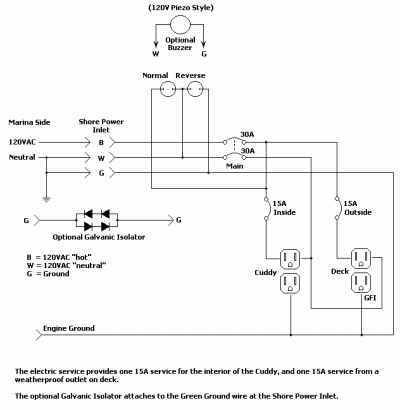
Here is the diagram I saw that lead to my confusion regarding the grounds & neutrals being connected on the shore side and not the boat.
I assumed the shore side included a sub panel. I also didn't notice it was 110v shore power diagram.:facepalm:
 

Attachments

  • shore2.gif
    shore2.gif
    8.9 KB · Views: 68
Last edited:
Makes sense. That's just a simplified diagram.
 

Latest posts

Back
Top Bottom