Nav lights/anchor light reversed?

The friendliest place on the web for anyone who enjoys boating.
If you have answers, please help by responding to the unanswered posts.

Capn Skippy

Member
Joined
Aug 30, 2020
Messages
22
Location
USA
Vessel Make
1995 Carver Santego 310, Crusader 350xli
Hi all,

In preface let me say what I know about DC wiring wouldn't fill a thimble which is why I'm appealing to the esteemed group here.

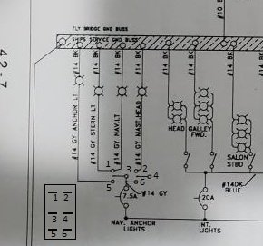
On to my question. When I flip the 3 position switch up towards nav only the anchor light (a mast on the helm station that only lights all around) and forward red and green lights come on. Flip it down and only the Stern light comes on.

I thought maybe anchor and Stern light wires were backwards on the switch, which has 6 total wires attached, with some bridge wires connecting a couple of the posts on the switch. Didn't work.

My ask is where the heck would you go to start in diagnosis?

Thanks for any insight you can share.

Mark
 
If your steaming / anchor lights are a combination, this may help

https://www.perko.com/images/catalog/pdf/Fig. 1125 Inst (USCG).pdf

Thank you for the reply... haven't been able to get back to the boat awhile, so pardon the lack of response...

I'm struggling to reconcile your diagram with actual wiring diagram (in fact, I struggle in general when it comes to wiring and the diagram for said wiring) along side the actual wires.

Based on Owner's manual list all wires (accept positive? which is red, but I don't see that in the list) are grey - with O being side nav, P stern, Q bow (wtf? don't have this?) and R being Anchor (which I assume is the mast?)

What I can't seem to wrap my head around are the jumper wires from one lead to another on the back of the switch... nor even which wire belongs to which lead? Nor how all of this corresponds to the diagram.

Like I said... electrical might as well be ancient sumarian - have no understanding of how to read it lol.

Can someone out there ELI5 to me?

Thanks again,
Mark
 

Attachments

  • 20201212_160436[1].jpg
    20201212_160436[1].jpg
    55.9 KB · Views: 17
  • 20201212_160405[1].jpg
    20201212_160405[1].jpg
    63.2 KB · Views: 15
  • 20201212_160326[1].jpg
    20201212_160326[1].jpg
    62.5 KB · Views: 17
  • 20201212_111805[1].jpg
    20201212_111805[1].jpg
    154 KB · Views: 18
  • 20201212_164222[1].jpg
    20201212_164222[1].jpg
    91.6 KB · Views: 21
  • 20201212_164234[1].jpg
    20201212_164234[1].jpg
    89.8 KB · Views: 26
Your wiring does not match the schematic. The schematic is also wrong with any kind of reality.

The switch listed in your text is a DPDT switch for the Side, Stern, and Bow Nav lights. While the anchor light is 'breaker switched'. You describe it as a Three position switch so the middle position is 'not connected' or 'off' position.

The schematic depicts a DPDT switch which allows you to have the Anchor light or the Nav light turned on. There is no path depicted in the schematic that would light the mast head light.

A DPDT switch is a 'Dual Position', 'Dual Throw'. That means it is actually two switches in one casing (dual throw basically means two switches internally actuated by one lever), and dual position means it can be ON up or ON down with different things connected to each side of the switch. Yours has a center 'off' position by your description of it. I've uploaded a clip of your schematic with the back of the switch drawn on it with the terminals and assigned it terminal numbers. That's if you look at the back of the switch. I added numbers to the schematic to show where the switch terminals are located in the schematic so you can see how the physical switch relates to the schematic.

So to explain the schematic:

Power is wired permanently to terminals 3 and 6.

With the switch in the 'UP' position (relative to the schematic) terminals 1 and 3 connected and also has terminals 4 and 2 connected. This would route power from terminal 3 to terminal 1. Terminal 1 is wired to NAV LT. and STEAM LT. Both of these would turn on. Terminals 2 and 4 being connected does nothing because 4 has nothing attached to it so the MAST HEAD would not turn on.

With the switch in the DOWN position (relative to the schematic) terminals 5 and 3 are connected and 4 and 6 are connected. Power flows from 3 to 5, and 5 has your ANCHOR light connected to it, so it would light up. Terminal 4 and 6 connected would again do nothing so your MASTHEAD light still would not light up.

The way the schematic shows it must be incorrect, so you can pretty much forget it. It shows that you can have either your ANCHOR or NAV lights on, depending on where you put the switch. I guess they expect you to use the breaker to turn off the lights entirely. The MAST HEAD light has no way of being lit according to the schematic.

All the wires are grey so if they aren't labeled, it's going to be a trial and error situation and making notes on which wire does what.

The jumper wire on the back of the switch is probably there to make things actually work since the schematic is clearly wrong.
 

Attachments

  • switchdiagram.jpg
    switchdiagram.jpg
    28.5 KB · Views: 88
Also... on the schematic, if you get rid of the connection to terminal 6 and put a jumper from terminal 3 to terminal 4, your mast head light would light up at the same time as the NAV/STEAM lights.
 
Someone switched the switch wires around on you. The red (assuming it is the 12+) should come into the center terminal.
The bow red/green should always light the same time as the stern white light with the switch in NAV.
The white masthead light should come on when the switch is in EITHER NAV or ANCHOR.
The white masthead light ONLY should come on in ANCHOR.

Yes power should be connected to the two center terminals of the switch. Lights should be connected to the outer four terminals. If the switch is 'UP', then the terminals 'DOWN' are powered. If the switch is 'DOWN', the terminals 'UP' are powered. In the middle none of the outer terminals are powered.

Ignore the schematic, it is wrong.
 
Back
Top Bottom