Modification on engine cooling system?

The friendliest place on the web for anyone who enjoys boating.
If you have answers, please help by responding to the unanswered posts.
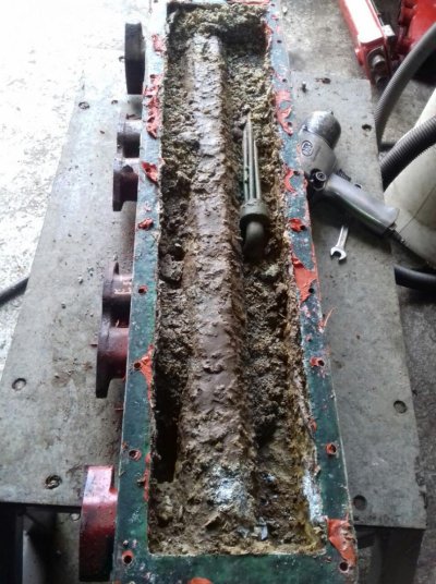
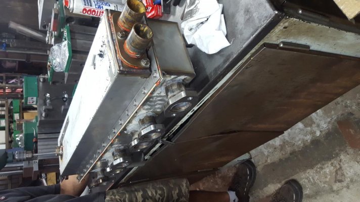
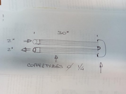
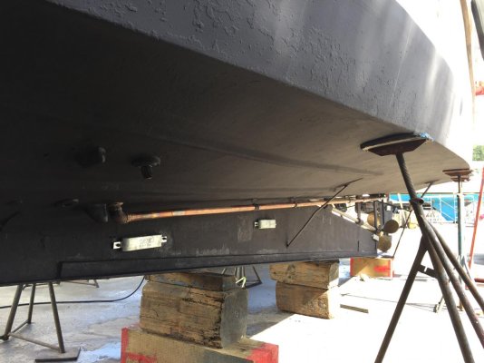
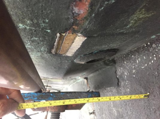
Wow, those pictures indicate that you are quite skilled at mechanical fabrication. But my initial reaction after seeing the pics is that the raw water system is too small and you don't have enough tube area in that heat exchanger bundle or stack as it is sometimes called. I am referring to the last pic for the bundle size as well as the first pic which shows smallish raw water piping/hose.


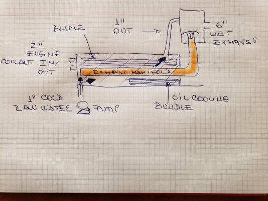
Are you seeing steam in your exhaust as it exits the boat as it starts to overheat? My guess at this point is that the temp of the raw water as it goes into that water injection stack is too high as a result of low flow and lack of tube area. Should be no more than 20 deg F higher than sea water inlet temps.


Your data collection will tell the story.


David
 
Last edited:
Wow, those pictures indicate that you are quite skilled at mechanical fabrication. Thank you, But I could not have done this with the help of some very skilled friends I have. My initial idea was to have it manufactured for me .... but the weird quotations I got made me change my mind!

But my initial reaction after seeing the pics is that the raw water system is too small and you don't have enough tube area in that heat exchanger bundle or stack as it is sometimes called. I am referring to the last pic for the bundle size as well as the first pic which shows smallish raw water piping/hose.
The raw water in / outlets to the exchangers are 1´´ hoses, and water circulation seems to be quite high (how much: I dont know and will measure soon) Exchangers get warm (not hot) after some hours of sailing. I check engine temperature by reading the gauges and every hour or so, by actually touching the whole system.


Are you seeing steam in your exhaust as it exits the boat as it starts to overheat? Actually did not check: there was bad weather and I was very concerned about not having enough power because of engines getting overheated.... no time to "Think" My guess at this point is that the temp of the raw water as it goes into that water injection stack is too high as a result of low flow and lack of tube area. Should be no more than 20 deg F higher than sea water inlet temps.

Your data collection will tell the story.


David

Here are some pictures showing the completely clogged original heat exchanger (Aluminium), which also had some cracks and how the new one looked.
 

Attachments

  • enfriado tapado.jpg
    enfriado tapado.jpg
    185.8 KB · Views: 34
  • new exchanger.jpg
    new exchanger.jpg
    108.2 KB · Views: 29
  • coolerdrw.jpg
    coolerdrw.jpg
    48.2 KB · Views: 30
That's a nice remanufacture of the OE system. That leads me to think maybe the OE system wasn't up to the standards of cooling the engine under severe duty.


A pyrometer is a simple device that reads exhaust gas temps. If the exhaust temps are to low, the engine may have problems boiling off condensation and soot can build up in the cylinders and exhaust system. At a certain exhaust temp, the engine creates enough heat to prevent that and even help burn off some of the soot in the engine. There is an upper limit that should not be surpassed due to the exhaust temps being high enough to damage the engine. A pyrometer helps to alert you when there's trouble. It can also help you determine when your engine is performing at it's best. I don't know what the best exhaust temps are for your GM350. An operator's manual or perhaps a service manual can give more detail on the proper exhaust temps recommended by the manufacturer.
 
I don't see how the coolant flow is forced around the tube bundle.
 
I didn't realize this was a home-made cooling system, so a lot more to validate that it's working correctly, and sized correctly.
 
I don't see how the coolant flow is forced around the tube bundle.

Nice job on your fabrication of the SS cooler box! I am thinking like Ski. How does the flow of cooling water get forced over the full length of the exhaust manifold and engine cooler bundle. I would have thought one way would be to have your cooling water enter the half of the box that has the engine cooling bundle and have a divider plate between the two halves with an opening at the rear. That would force your coolest water to flow from the inlet at the front over the tube bundle to the rear of the cooler and then through an opening to the other half of the cooler box, exiting over the exhaust manifold and out the front to be discharged. You could easily add a coolant port in the lower half of the box and a divider plate to do this.

I am wondering about the size of your cooling bundle also. I have gleaned some numbers on heat exchange from working on my own boat cooling system which has an external heat exchanger. The temperature differential between coolant temp and sea water temp is a big part of cooling but also the area of exposure for the heat exchanger is the other half of the equation. If you calculate the outside surface area of individual tubes times X number and times the length of your tube bundle and convert that to square feet you have an important value. In warm sea water you need about 1 square foot of surface area of your hot engine water for each 3-5 HP of power produced in an external keel cooler system. On your cooler bundle I am making some assumptions around the info you provide. 1/4" tube may have a OD circumference of 1" times 30" length times 30?? tubes = 900 square inches which divided by 1728 to get sq ft = about 1/2 a square foot. That is not very much area. For my 6.5 liter NA Mitsubishi 6D14 that makes about 120 HP at WOT I have about 45 feet of 1 1/2" copper pipe in the water which calculates to about 19 square feet of surface area. That is not enough when I add in the exhaust cooling and transmission and hydraulic coolers so am just in the process of adding an additional Fernstrum keel cooler. The new cooler is 7" wide x 3" deep x 84" long with a lot of surface area. Last night I just finished fabricating my new 2" port full flow temperature control manifold to go with the new cooler.
 
If my thinking is correct, the water flows up from the bottom and out through the top on opposite ends from each other. From there, I'm not sure where the routing leads to. There could be air trapped in the system that may be causing the overheating.
 
That's a nice remanufacture of the OE system. That leads me to think maybe the OE system wasn't up to the standards of cooling the engine under severe duty.


A pyrometer is a simple device that reads exhaust gas temps. If the exhaust temps are to low, the engine may have problems boiling off condensation and soot can build up in the cylinders and exhaust system. At a certain exhaust temp, the engine creates enough heat to prevent that and even help burn off some of the soot in the engine. There is an upper limit that should not be surpassed due to the exhaust temps being high enough to damage the engine. A pyrometer helps to alert you when there's trouble. It can also help you determine when your engine is performing at it's best. I don't know what the best exhaust temps are for your GM350. An operator's manual or perhaps a service manual can give more detail on the proper exhaust temps recommended by the manufacturer.

Thanks for the explanation. Of course I am familiar with pyrometers, but did´nt know they were used for monitoring combustion (great application though) I will see if I can get required info from engine in order to built one in
 
I don't see how the coolant flow is forced around the tube bundle.

The coolant gets in at the front / bottom and leaves at the back / top trough the goose neck hose seen in the picture
 
If my thinking is correct, the water flows up from the bottom and out through the top on opposite ends from each other. From there, I'm not sure where the routing leads to. There could be air trapped in the system that may be causing the overheating.

your thinking is 100% correct. from the rear top end water flows trough a goose neck hose into a vertical SS cylinder / chamber That contains a sort of snorkel (to prevent water flowing int engine). There it gets mixed with exhaust gases prior to leaving via the 6´´ exhaust hose

I prime / purge the cooler box every now and then (mainly when cleaning raw water intake filter) and no air seems to be entrapped. Neither the surface of the box nor the vertical mixing cylinder get too hot while working, as they can be touched with the bare hand. The surface of the box is way cooler (may be 25ºC) at the top front than at the back top (approx. 50ºC)
 
Last edited:
Nice job on your fabrication of the SS cooler box! I am thinking like Ski. How does the flow of cooling water get forced over the full length of the exhaust manifold and engine cooler bundle. I would have thought one way would be to have your cooling water enter the half of the box that has the engine cooling bundle and have a divider plate between the two halves with an opening at the rear. That would force your coolest water to flow from the inlet at the front over the tube bundle to the rear of the cooler and then through an opening to the other half of the cooler box, exiting over the exhaust manifold and out the front to be discharged. You could easily add a coolant port in the lower half of the box and a divider plate to do this.

As I replied to Sky, the water flows trough the box from front to back and bottom to top

I am wondering about the size of your cooling bundle also. I have gleaned some numbers on heat exchange from working on my own boat cooling system which has an external heat exchanger. The temperature differential between coolant temp and sea water temp is a big part of cooling but also the area of exposure for the heat exchanger is the other half of the equation. If you calculate the outside surface area of individual tubes times X number and times the length of your tube bundle and convert that to square feet you have an important value. In warm sea water you need about 1 square foot of surface area of your hot engine water for each 3-5 HP of power produced in an external keel cooler system. On your cooler bundle I am making some assumptions around the info you provide. 1/4" tube may have a OD circumference of 1" times 30" length times 30?? tubes = 90 are 5.7 liter0 square inches which divided by 1728 to get sq ft = about 1/2 a square foot. That is not very much area. For my 6.5 liter NA Mitsubishi 6D14 that makes about 120 HP at WOT I have about 45 feet of 1 1/2" copper pipe in the water which calculates to about 19 square feet of surface area. That is not enough when I add in the exhaust cooling and transmission and hydraulic coolers so am just in the process of adding an additional Fernstrum keel cooler. The new cooler is 7" wide x 3" deep x 84" long with a lot of surface area. Last night I just finished fabricating my new 2" port full flow temperature control manifold to go with the new cooler.
The info you provide is really valuable to me. My engines are 5.7 liter. I sail the Rio de la Plata / Uruguay River / Parana River basins (there is also a large delta in-between these rivers). Raw water temperature ranges from 15ºC during (short winters), reaching 25 to 30ºC in summer. Now that I have solved most of the urgent matters on the boat I started "sharpening the pencil tip" to make all systems more efficient Many boats like mine were built in the 80´s trough 90´s ... but the yard went bankrupt and there is only one boat (completely different to mine also different engine) in my area. The rest are used as Pilot or Supply boats in Fireland (Tierra del Fuego) 4000 km south from where I live ... and there is no way of getting any info.
 
According to Transaxial´s information I made the following calculations: 1 sq foot every 3 to 5 HP (taking the worst scenario I will calculate 3 HP/Ft).
1 sq foot is 0.09 sq meters.
My engines are rated @ 120 HP.
1 meter 2" pipe has an external surface of 0.17 sq meters.
So 120 HP / 0.17 = 40 lineal meters. Which is 4 rows of tubes at the keel x 10 meters in length ....
Am I right?

I have the feeling this will be like dragging an anchor!
 
The coolant gets in at the front / bottom and leaves at the back / top trough the goose neck hose seen in the picture

Do you have any photos showing this flow path. I sense this is the critical issue on your overheats.

In most heat exchangers, there are alternating baffles that divert flow, forcing it to cross the tube bundle several times. Best heat transfer as it has to move perpendicular to the tubes. I saw no such baffles or flow diverting devices on your fabrication.

There are no baffles in these exchangers (nor where in the original casted aluminium ones). When fabricating the SS version, I copied as good as possible the original parts.
By then I only had driven the boat just to get it on the hard. The previous owner was a jerk so he probably did not notice it overheated! On the other hand, it was so neglected that anything could have been possible... but these were no reasons for not buying it! It was love at first sight what I felt for it!

I am attaching a cross section of the "box" as I recall it. (drawing is Not what I do best!):blush:
 

Attachments

  • 20190215_114024.jpg
    20190215_114024.jpg
    122.7 KB · Views: 22
Thanks for the explanation. Of course I am familiar with pyrometers, but did´nt know they were used for monitoring combustion (great application though) I will see if I can get required info from engine in order to built one in


You're welcome. :thumb:


your thinking is 100% correct. from the rear top end water flows trough a goose neck hose into a vertical SS cylinder / chamber That contains a sort of snorkel (to prevent water flowing int engine). There it gets mixed with exhaust gases prior to leaving via the 6´´ exhaust hose

I prime / purge the cooler box every now and then (mainly when cleaning raw water intake filter) and no air seems to be entrapped. Neither the surface of the box nor the vertical mixing cylinder get too hot while working, as they can be touched with the bare hand. The surface of the box is way cooler (may be 25ºC) at the top front than at the back top (approx. 50ºC)


:thumb:Sounds like a standard heat exchanger set up.


I wonder if scale and mineral deposits have built up in the water jackets around the cylinders. I haven't seen it mentioned but it may have been.
 
That is different. Typical HX design has the sea water in the tubes (called the tube side), and the cooled fluid surrounding it (called the shell side). You have done it backwards.

Part of the reason for the standard arrangement is tubes are easier to clean (or should be) than the shell side. And corrosion is easier to control in tubes than in the box.

I think your heating problem is based on the design. The flow of sea water in the box is not channeled to flow around the tubes. The fwd upper area of the bundle will hold heated sea water and nothing will encourage it to move aft.

How long has this unit been in service? Did it work ok initially? Might already be fouled on the shell side?

I think your options are to add a commercial HX or go keel cooled. Not a fan of the can type mixer, either. Get a corrosion hole in it and it is an engine killer.
 
I agree with Ski. Is it possible you misinterpreted the operation of the original design, and have things flowing incorrectly now?


Also, in the few engines I've seen, the exhaust manifold is coolant jacketed, not sea water jacketed. This further suggest that you have the wrong fluids in the various section.


Another consequence of the existing flow is that the raw water that is cooling the exhaust manifold and the engine coolant are co-mingled. I expect the exhaust will reject more heat, thereby leaving less fluid temp differential to pull heat from the coolant. Designs I have seen always have the coolant heat exchanger first in line for the raw water so it see's the coolest water. Then comes everything else.


And a 1" raw water line for a 120hp engine? It's totally seat of the pants, but that seems very small compared to other engines I've seen.


I think the simplest fix would be to have an off-the-shelf heat exchanger sized for the engine. Then place that first in the raw water loop, and feed the raw water output to the existing box to cool the manifold. Better yet, run the engine coolant output through the manifold box, then through the heat new exchanger. Your raw water jacketed exhaust is another engine killer waiting to happen. Any leak and you have salt water in the engine.
 
Last edited:
I think that Ski and Twistedtree have nailed the solution. Not sure what is easier: rework the old system around a commercial heat exchanger or install keel cooling.


If you were to do the latter then you would have to keep the raw water system to cool the exhaust (or go with a dry stack). If so you could route the raw water first through your exhaust manifold which will avoid a lot of plumbing. But as noted that isn't ideal as a leak will ruin the engine.


At this point in the diagnosis/conversation I don't see any point in doing the temp/flow profile I recommended above. Rework the system first.


David
 
Passed along by a marine engineer....


"I just went back and looked at the OP's photos and see that he is already using U-tube bundles so the counter flow discussion is moot. Contrary to the drawing I sent you, he can keep the raw water flow as is, in at the front, out at the back and save on tubing"
 
According to Transaxial´s information I made the following calculations: 1 sq foot every 3 to 5 HP (taking the worst scenario I will calculate 3 HP/Ft).
1 sq foot is 0.09 sq meters.
My engines are rated @ 120 HP.
1 meter 2" pipe has an external surface of 0.17 sq meters.
So 120 HP / 0.17 = 40 lineal meters. Which is 4 rows of tubes at the keel x 10 meters in length ....
Am I right?

I have the feeling this will be like dragging an anchor!

I think you are high on your calculation for your 25-30 C water temp. This calculation is for WOT operation and of course you can get by with less at cruise speed. It seems a lot of designs are minimal on the cooling system which leads to overheating when rust and scale reduce efficiency in time. As evidenced in the picture you posted of your old cooler box.

If I do the calculation in feet, then 2" OD pipe has just over 1/2 sq ft of area per running foot, so to get to 40 sq ft of surface area you need 80 feet of that cooling pipe, or 25 meters. There is also a factor of inefficiency in pipe larger than about 3/4", in that the hot water in the center of a 2" pipe tends to stay in the center and does not cool properly. That is why a spiral diffuser is often used, or a spiral twist such as Walter uses in their cooling tubes, to mix the hot water in the cooler tubes. Not to put you off doing it yourself, it does not have to be rocket science, but to add a little more pipe to be sure you have enough is a good safety margin. This weekend I am going to my boat to install a new Fernstrum copper/nickel cooler that cost $5,000. You can buy a lot of pipe for that. I did it because it would work well with existing through hulls and fit into the space I have and give me a minimal pressure drop of 2 psi at 60 gpm flow rate.
 

Attachments

  • IMG_0732.jpg
    IMG_0732.jpg
    113.2 KB · Views: 18
  • IMG_0719.jpg
    IMG_0719.jpg
    123.9 KB · Views: 14
  • IMG_0717.jpg
    IMG_0717.jpg
    148.1 KB · Views: 16
Last edited:
I think adding a sendure (I think that’s the name) heat exchanger would be really straight forward, and substantially easier than converting to keel cooling. You just need so engineering (not guessing) on the exchanger size and the required raw water flow. And be sure the calcs allow for coolant cooling of the manifold in case you want to do that now or later. The rest is simple plumbing and mounting brackets.
 
Thanks to all for the interesting info. Out of business due to toe surgery a while ago. I'll do my best to reply to all tomorrow! Nurse is pissed off she will take phone away!
 
Thanks to all for the interesting info. Out of business due to toe surgery a while ago. I'll do my best to reply to all tomorrow! Nurse is pissed off she will take phone away!

You definitely do not want to piss your nurse off!! ;)

Ski, twistedtree, djmarchand and psneeld all have very good suggestions, information and advice. (Along with many others in this thread) I am simply trying to help you with some of the info I have learned in doing a redesign of my keel cooled boat that has heating problems. What I do know is that it takes a lot of cooling to keep a 120 HP engine happy at WOT. And as has been stated that when you are using the same coolant flow to remove exhaust manifold heat you need at least 50% more capacity and water flow. Information is very scarce out there and those that know seem to be quite tight lipped about it, maybe fearing for their exclusive knowledge and their jobs. I also know that some of the people that should know this info are not giving correct info. Just trying to share what I believe to be correct and not trying to convince you that a keel cooler is the only solution.

Another important part of cooling is the flow of liquid coolant. This is usually stated as BTU. One BTU is the amount of heat required to raise the temperature of one pound of water one degree F over one hour. So the flow of water required to carry away the heat the engine water jacket produces is calculated with the formula Gallons per minute = BTU divided by 500(water and 450 for anti freeze) times Delta T (difference in temp of water leaving engine compared to return) The water pump on my 120 HP Mitsubishi is rated at 58 gpm. I have checked that on a new and a rebuilt pump on my own test bench and find the pumps will do at least that flow at 8 psi. This may be helpful in determining if your sea water flow is adequate. Your raw water flow at 1" sounds low to me as well. I keep coming back to the same conclusion, that at low pressure of 2 to 8 psi out put of the engine water pump you need a 2" flow to get to 58 gpm. If you have a higher pressure raw water pump it is possible to get enough flow at 1" though.
 
ND
You are getting some good information. I can add, based upon HXer design experience on both very big industrial and small HXers like on our boats, that a safety factor needs to be added. Generally add to the "paper" design something around an additional 20 to 30% which will cover the gradual scaling up as time passes.

Also, if not mentioned, raw water and coolant flow rates on most of our vessels increase as RPM increases. So calculate the size of the unit for the higher flows to insure no inordinate rise in friction head within the HXer itself.
 

Latest posts

Back
Top Bottom