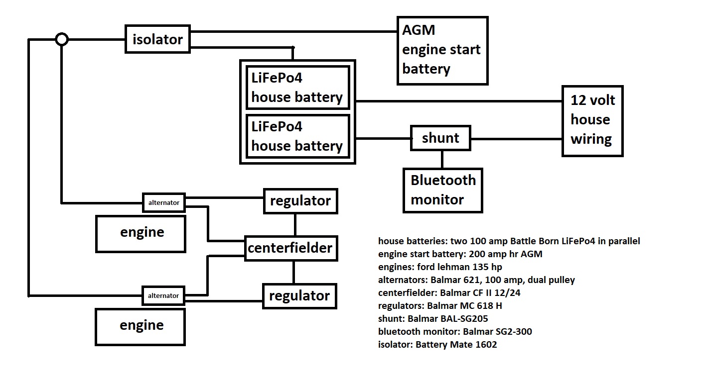
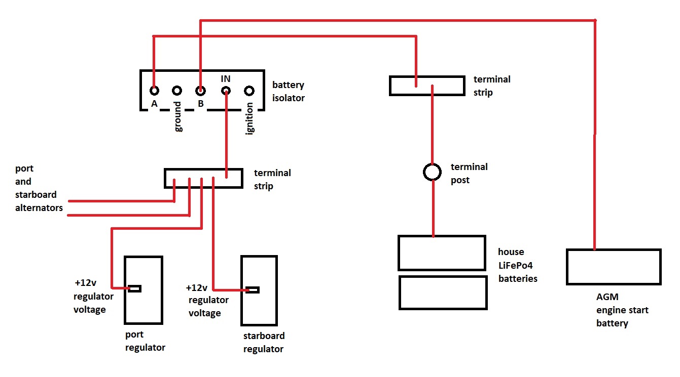
I think the primary problem is that your sense wire from the alternators is on the alternator side of the combiner, and it needs to be on the LFP battery side. That's why the voltage at the shunt is so much lower than the voltage at the alternators. The sense wire is terminal 9 on the MC 618, not to be confused with the main power supply on terminal 2...
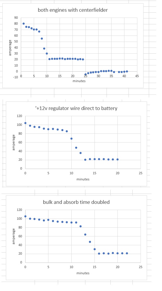
I ran a few tests over the weekend, which are summarized in the graphs below.
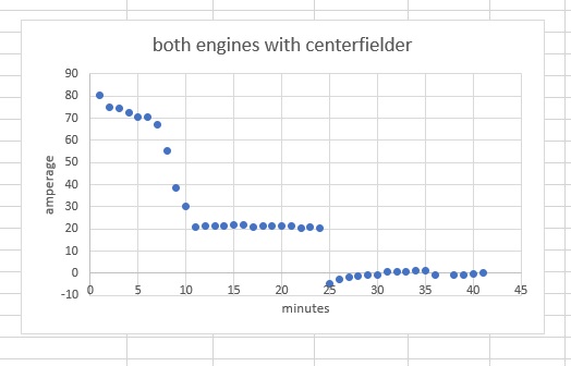
The first graph is just a copy of the charging profile that I posted at the beginning of this thread. This was the only test I did where I introduced a 25 amp load on the house batteries after 25 minutes.
The second graph had the same testing environment as the first EXCEPT I ran the 2 voltage sense wires from terminal 9 on both regulators directly to the LiFePo4 battery post. I was surprised at the increased amperage it generated.
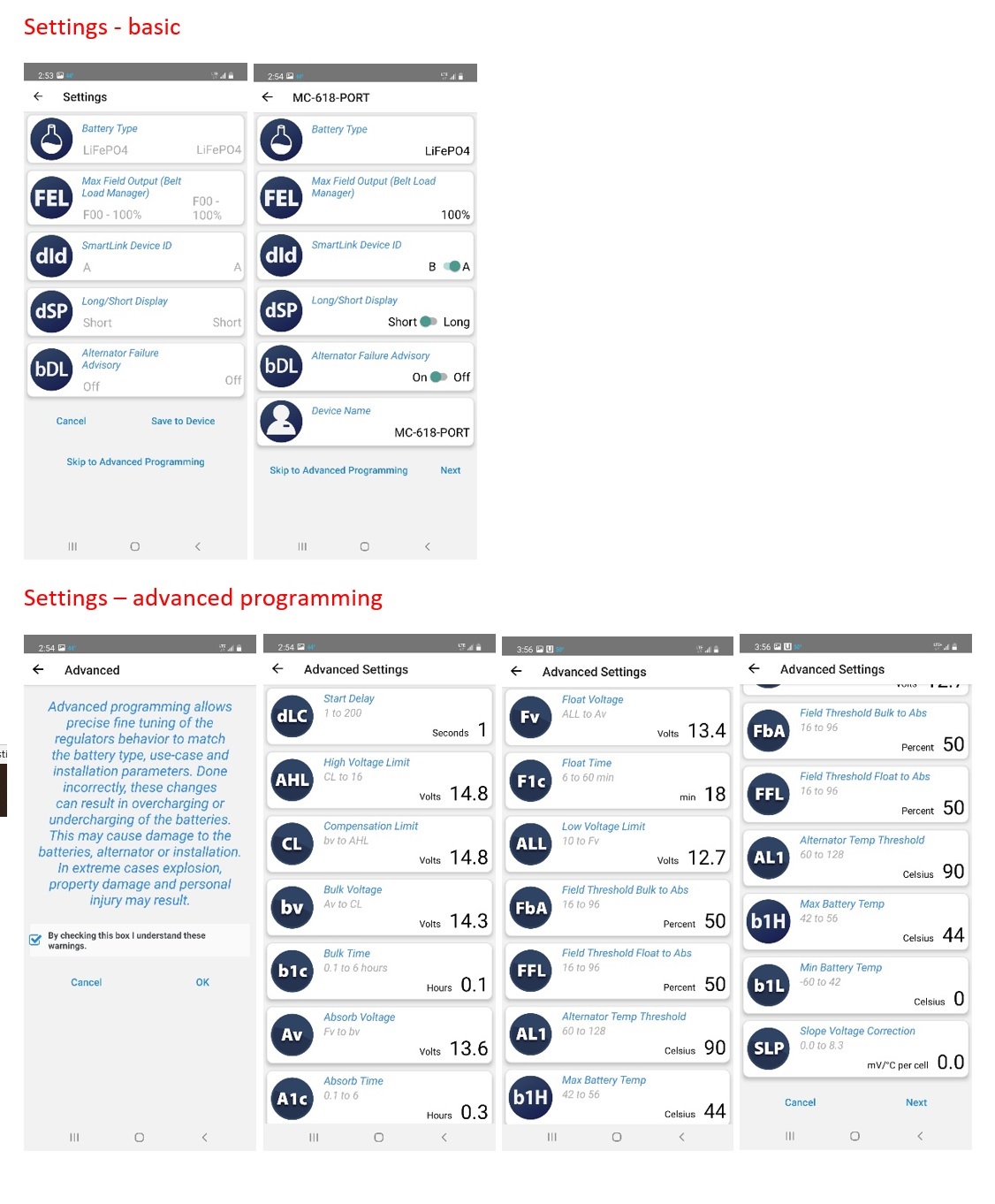
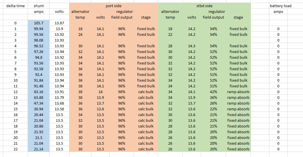
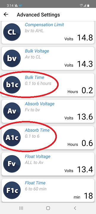
The third graph had the same testing environment as the second graph EXCEPT I doubled the "Bulk Time" (B1c) setting from .1 hours to .2 hours, and I doubled the "Absorb Time" (A1c) setting from .3 hours to .6 hours. I was surprised that the graph didn't change much. After I saw that third graph, I went back to the boat to see if my B1c and A1c increases had somehow disappeared, but they were still there.
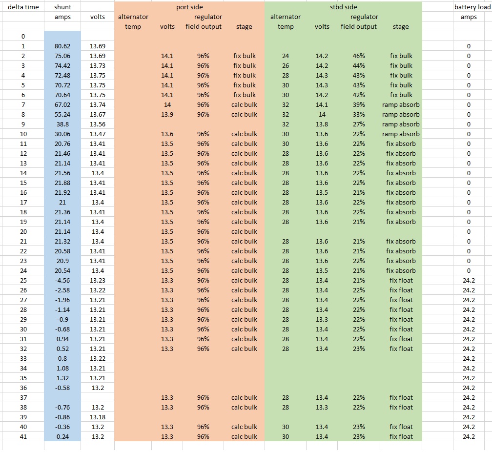
The spreadsheet with all the colors contains details of my charging environment that I captured while doing that third test.
Also, for what it's worth, I called Battle Born, told them I had 2 of their 100 amp LiFePo4 12v batteries connected in parallel, and asked them how much charging amperage they could accept. Their answer was 150 amps, until either the batteries reached full charge or the temperature limits were exceeded.
At this point, I'm pretty happy with the initial amperage I'm seeing, but I think it's a little strange it doesn't last longer. Do you think I should accept these results as "good enough", or continue tweaking the parameters in "advanced settings"?