1976 Hatteras 58 LRC Stabilizer Install

The friendliest place on the web for anyone who enjoys boating.
If you have answers, please help by responding to the unanswered posts.
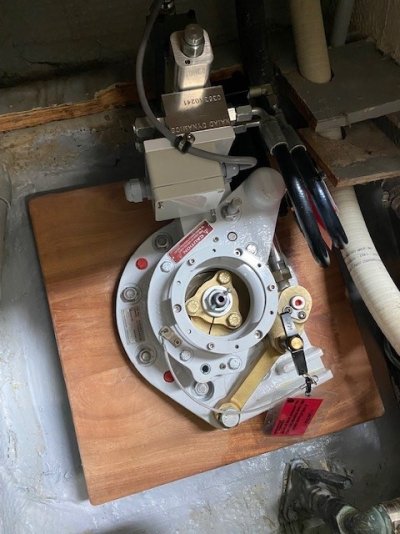
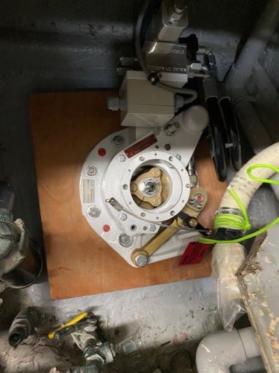
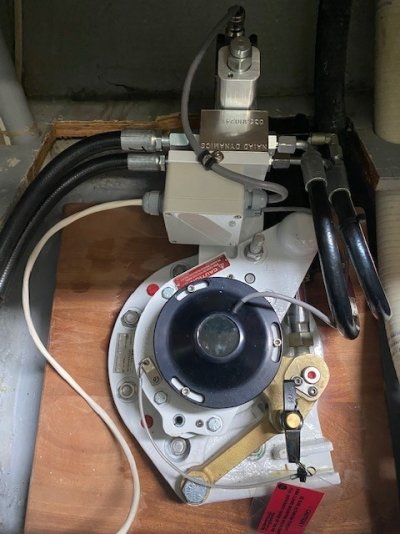
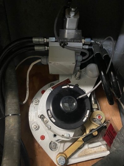
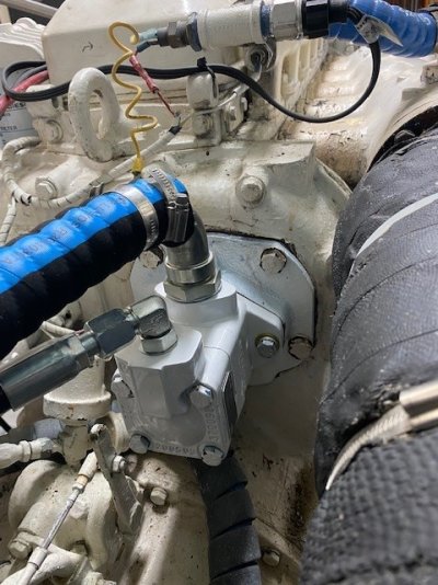
Great install, thanks for posting. Those blocks seem really thick. Do all Naiad's require blocks that thick? I have been working on replacing the seals in my Keypower stabilizers the last few days, and they have much thinner backing plates. From looking at the pictures, I think the difference is the Naiad's look like they have both bearings under the actuator lever arm, which adds depth, while the Keypower has the second bearing above the lever arm. If you have enough room for it inside the boat the Naiad design looks easier to service to me. I don't think the Naiad would have fit that well in my boat.
 
I had Naiad 251 on my last boat (Cheoy Lee 50) 30 year old simple system. It worked flawless. The only upgrade I did was move from Belt drive off the crank to rubber direct drive. The only thing I would have liked was a electric clutch arrangement, I would have liked to disconnect the hydraulic pump one time, when I had a burst ram seal. Had to remove the direct drive. No Biggie really 20mins and up and running. Other than that, great systems and worked well in the eastern Caribbean with good seas running. My current boat (Cheoy Lee 65) has the 252 system albeit 1981 edition. Just had them rebuilt by Stabilzed Marine. They are excellent on service and support. They also give advice freely, ship parts and instructions how to fit etc. I've always liked the reliability of Naiads, and the older models that you can fix yourself.
 
Got any updates on your progress?
 
Sorry for the long pause in updates. I had some real life issues to take care of.

The install has progressed nicely. The actuators were installed and fiberglassed to the inside of the hull. You can't really see the fiberglass work in the pics since they tabbed them onto the hull and up on the sides of the support block.

I was not on the boat when they installed the fins and the yard did not get any pics of the fins installed.

The boat was re-splashed about two weeks ago. Then the oil cooler/reservoir was installed along with all the associated hydraulic hoses. The wiring was also installed and run up to the pilot house and upper helm. When I left there last week, they had installed both the upper helm and pilot house controls. All that was left to do was for the electronics guys to do the actual hook ups.

I'm actually on my way there now and will get some more updates and pics this weekend.
 

Attachments

  • Actuator Installed Port 03 Outside Support Blocks.jpg
    Actuator Installed Port 03 Outside Support Blocks.jpg
    55.3 KB · Views: 29
  • Actuator Installed Port 03 Outside Support Blocks Closeup.jpg
    Actuator Installed Port 03 Outside Support Blocks Closeup.jpg
    102 KB · Views: 29
  • Actuator Installed Starbaord 01.jpg
    Actuator Installed Starbaord 01.jpg
    52.7 KB · Views: 27
  • Actuator Installed Port 01.jpg
    Actuator Installed Port 01.jpg
    48.5 KB · Views: 26
I'll post up more pics of the oil cooler/reservoir, oil pump and controls in a day or so.
 
.....
 

Attachments

  • Actuator Installed Port 03.jpg
    Actuator Installed Port 03.jpg
    92.1 KB · Views: 32
  • Actuator Installed Starbaord 03.jpg
    Actuator Installed Starbaord 03.jpg
    82.4 KB · Views: 28
  • Oil Reservoir Mounted 01.jpg
    Oil Reservoir Mounted 01.jpg
    90.4 KB · Views: 28
  • Controller Pilot House.jpg
    Controller Pilot House.jpg
    54.4 KB · Views: 31
  • Wiring Side Cabin 01.jpg
    Wiring Side Cabin 01.jpg
    96.5 KB · Views: 26
  • Wiring 02.jpg
    Wiring 02.jpg
    98.1 KB · Views: 29
Is the wood block under the wood "panel" we are seeing, and how is it all laminated together? Or is it just sandwiched between the exterior plate and the actuator based plate?
 
Is the wood block under the wood "panel" we are seeing, and how is it all laminated together? Or is it just sandwiched between the exterior plate and the actuator based plate?

Are you talking about the mahogany wood block in Post #22?

If yes, then that support block is provided by Niaid from the factory and yes it is laminated. Then it is fiberglassed to the interior of the hull.
 
Looks great! Nice install so far. Thanks for sharing!!
 
Here's s few more pics of the hydraulic pump installed, oil cooler/reservoir piped, plumbed and wired and actuators plumbed and wired...
 

Attachments

  • Actuator Installed Port 04 complete.jpg
    Actuator Installed Port 04 complete.jpg
    86.2 KB · Views: 24
  • Actuator Installed Starbaord 04 complete.jpg
    Actuator Installed Starbaord 04 complete.jpg
    75.3 KB · Views: 24
  • Oil Reservoir Mounted Closeup.jpg
    Oil Reservoir Mounted Closeup.jpg
    62 KB · Views: 25
  • Oil Reservoir Mounted Piped and Plumbed.jpg
    Oil Reservoir Mounted Piped and Plumbed.jpg
    95.8 KB · Views: 22
  • Hydraulic Pump.jpg
    Hydraulic Pump.jpg
    111 KB · Views: 22
I'm still a bit confused by the exposed wood. Is it glassed up the sides where we can't see it? Installations I've seen before have the wood block completely encased/sealed in glass/epoxy.
 
I'm still a bit confused by the exposed wood. Is it glassed up the sides where we can't see it? Installations I've seen before have the wood block completely encased/sealed in glass/epoxy.

Exactly.. the block is glassed up the sides all around. It was not glassed on the top of the wood block. I was told that it was not necessary. This is the same design AYB has used for years with many Niaid stabilizer installs.
 
Exactly.. the block is glassed up the sides all around. It was not glassed on the top of the wood block. I was told that it was not necessary. This is the same design AYB has used for years with many Niaid stabilizer installs.


Unfortunately one is only going to know how well the reinforcement works is when or if a fin comes in contact with something.
 
Unfortunately one is only going to know how well the reinforcement works is when or if a fin comes in contact with something.

Well.... AYB has been installing Niaid stabilizer systems for over 30 years. I have to defer to their long-standing experience with stabilizer system installation and relationship with Niaid on this one.

From what I've seen from their craftsmen and management, I don't think they are cutting any corners on this point... and really no need to as the project labor is based on T&M.
 
Last edited:
2-25-22 Update -

All the wiring was completed yesterday. Both controllers (Pilot House and Flybridge) were wired and interfaced. The NIAID control box was also interfaced with my Garmin Pilot House MFD so the GPS speed could be used for automatic centering of the fins below 3 kts. They also installed a small 32-24 VDC DC-DC converter for the system.

I had to do some wiring and breaker modification in the 32 VDC Ships Servce #1 breaker panel. The original stabilizer system was powered from a 5A breaker which was in the #6 position on the panel. This system required at least a 7.5A breaker. The original breaker wiring (Wire #312) went up to a flybridge terminal block. For this installation, it was decided to place the NIAID control box in the Pilot House "cable spread room". Rather than running new wires, I traced out some existing wires and did a slight wiring ad breaker modification.


At some point, a previous owner had removed the Pilot House Instrument Lighting system. This was powered by a 10A breaker in the same panel. The Instrument Lighting wiring (#314) went from the 32 VDC Ships Service Panel #1 to the Pilot House TB#4. So I swapped the breakers in the panel and swapped the wiring so I could use the existing "Stablizer" breaker slot on the 32 VDC Ships Service Panel #1. This is a relatively minor detail, but wanted to share this with the group.

Looks like Monday is "hot functional" test at the dock and if all goes well, we will also do a sea trial on Monday.
 

Attachments

  • Controller Flybridge.jpg
    Controller Flybridge.jpg
    45.1 KB · Views: 15
  • Controller Pilot House.jpg
    Controller Pilot House.jpg
    54.4 KB · Views: 19
  • Controller Wiring 03.jpg
    Controller Wiring 03.jpg
    71.6 KB · Views: 16
  • Controller Wiring 02.jpg
    Controller Wiring 02.jpg
    81 KB · Views: 15
  • Controller Wiring 01.jpg
    Controller Wiring 01.jpg
    61.7 KB · Views: 15
  • Controller Wiring 04.jpg
    Controller Wiring 04.jpg
    103.5 KB · Views: 14
  • Controller Wiring 05.jpg
    Controller Wiring 05.jpg
    128.6 KB · Views: 15
There was some discussion on the wood block mounting and support in previous posts. As discussed, there seems to be different methods for supporting the actuator/fin assembly.

As I was reviewing the NIAID manual last night, ran across a drawing that provides some insight as to the different support methods. See below for some excerpts from the drawing.
 

Attachments

  • Niaid Support Mounting 02.jpg
    Niaid Support Mounting 02.jpg
    147.6 KB · Views: 15
  • Niaid Support Mounting 03.jpg
    Niaid Support Mounting 03.jpg
    137.7 KB · Views: 16
  • Niaid Support Mounting 01.jpg
    Niaid Support Mounting 01.jpg
    94.6 KB · Views: 16
Naides is the only way to go. I had them in my 43 Selene they worked incredible. I now have a 53 Selene in it had Westmars I couldn't belive how bad they were. I had them replaced in my 53 with Niades they work incredible.
 
We almost bought a 58LRC about a year and a half ago. My wife didn’t like it…. It had most if not all the 32volt systems removed. But I was still amazed at how many different electrical panels were aboard. I absolutely loved the engine room but that wasn’t enough to convince my wife.
 
System commissioning was today. Ran into a couple problems, one a system configuration issue and one a little more complex.

For the complex one.. it was originally planned to take cooling water directly off the heat exchanger using one of the zinc locations. During system checkout, it was observed that we had no cooling water discharge overboard. We moved the pickup location to a spot immediately downstream of the raw water pump. This was still not sufficient "pressure" to push the water through the oil reservoir cooling coil. The oil reservoir/cooler is mounted about 4 feet above the cooling water pickup location. At this point it appears a passive method of scavenging cooling water from an existing location may not be feasible.

The next possibility is installing a dedicated cooling water pump for the stabilizer oil reservoir/cooler.

For those with stabilizer systems, was wondering how your oil cooling water systems are set up?.... a dedicated pump ... or scavenging off another system?

Thanks in advance!
 
Last edited:
For those with stabilizer systems, was wondering how your oil colling water system are set up?.... a dedicated pump ... or scavenging off another system?

Thanks in advance!

We have Naiad stablizers as well and have a dedicated cooling circulation pump.
 
I have a dedicated electrical cooling pump. At the time the yard said that would be fine, but also mentioned that the gold standard would be a hydraulic cooling pump.
 
My raw water pump had two plugs on the back. I used the outflow plug and also installed a ball valve to throttle the water if it was to much. I used 1/2 lines. Not a lot of water idling but a strong stream at rpm.
 
Thanks for everyone's replies on the cooling water pump.

As noted in previous post, had a minor configuration problem that turned out to be an ambiguous wiring drawing issue.

System has passed the operational portion of the check out. The decision has been made to install a dedicated electrical raw water cooling pump for the oil cooler.

Almost there!.....
 

Attachments

  • Controller Pilot House Operational 01.jpg
    Controller Pilot House Operational 01.jpg
    48.5 KB · Views: 15
  • Controller Pilot House Operational 02.jpg
    Controller Pilot House Operational 02.jpg
    51.4 KB · Views: 14
  • Controller Pilot House Operational 03.jpg
    Controller Pilot House Operational 03.jpg
    69 KB · Views: 12
Did you ever finish this up? If so, how is it all working?
 
I did same as Magna On my system.
 
System commissioning was today. Ran into a couple problems, one a system configuration issue and one a little more complex.

For those with stabilizer systems, was wondering how your oil cooling water systems are set up?.... a dedicated pump ... or scavenging off another system?

Thanks in advance!

Even though 8 months later ---

On our 7' Wesmars with a Vickers PTO the entire raw water flow goes through the hydraulic cooling heat exchanger. RW pump discharge to inter cooler to transmission HXer to engine HXer to Wesmar HXer to exhaust elbow. Oil temps constant at 105 to 110F. Water flow out exhaust has always been good with never a sign of heat up as measured with IR gun at various raw water loop points.

I've friends who had a Naiad install done quite similar to yours. (The entire block was glassed over) they too had heating issues. Low water flow due to small diameter piping and hoses especially when compared to mine was the major difference. If you could redo your RW runs in and out of HXer to larger lines and total loop volume that may be worth considering. This assumes your HXer is sized to accept full flow and the RW pump is with enough head pressure to handle the oil HXer.

Unfortunately cooling water flow and design tends to receive lesser attention during these after market installs. In essence, RW pump capacity, system line size and length and exhaust back pressure are interrelated. And boat specific.

Fortunately our system was with many successful predecessor installs penned by Art DeFever and done at the factory nearly 20 years ago. If AYB took possession of this install they might well go back to the primary design and calculations for your boat specific cooling water flow requirements to work properly regardless of Naiads "typical" flow diagrams.

Good luck with the external pump loop, seems the easiest route given where you are. Do those of you with ABT and Key Power installs have a separate pump and cooling loop?
 
Last edited:
Back
Top Bottom