Amp gauges never read above zero?

The friendliest place on the web for anyone who enjoys boating.
If you have answers, please help by responding to the unanswered posts.

FBoykin

Senior Member
Joined
Feb 13, 2014
Messages
165
Vessel Name
Hannah Jane
Vessel Make
2000 Grand Banks 42 Classic
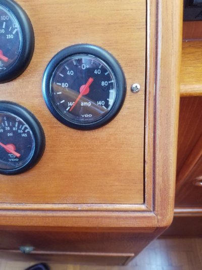
I have these amp gauges at my salon helm. Diesels off, they rest at zero. When diesels start, gauges come up to zero, but no higher. I have it in my head that they should read above zero as alternators charge up the batteries. Am I wrong?

The GB 12v wiring diagram shows they're each connected through a shunt to each alternator.

Thanks!

VDO Amp Gauge.jpg
 
I would check your connections first, then use my Amp Clamp to measure DC current flow to verify alternators of pushing voltage measured in Amps.
If you have twin engines you can swap the wires maybe to help diagnose.
 
Yeah - first step if it was my boat is to figure out if it's a sensor error or if your alternators are malfunctioning. Does your voltage jump up to ~13.5V+ from ~12.5V after you start? If not your alternators aren't working.
 
My suggestion is as follows:
Could be the alternator, the voltage regulator, wiring or voltage meter.
Start by checking the output of the alternator and regulator. If it is good then, clean up the wire contacts between the alternator and voltage meter. Hook it up, read the voltage meter. Still no reading, I think you narrowed it down to the voltage meter.
 
Last edited:
Dan it is an ammeter, not a volt meter. It appears someone has disconnected the lead to the battery bank from the meters.
 
Dan it is an ammeter, not a volt meter. It appears someone has disconnected the lead to the battery bank from the meters.

I stand corrected, WE think.
I will learn more as I get deeper into my project of moving the output to the VesselView to analog gauges.
We want both voltage and amperage output. Then the battery voltage. There are meters that will determine the amount of amp left in the house batteries.

To quote from another source, "Voltage is a measure of the pressure that allows electrons to flow, while amperage is a measure of the volume of electrons."

As someone said, it is not the voltage but rather the amperage that will kill you.
 
Last edited:
Good advice above. How long have you been noticing this? What is your boat-use profile? I ask because if indeed you are not getting any amps heading to your batteries while the engines are running, and you are on shore power nightly charging from the boat's battery charger, you can get away with bad alternators, regulators, and/or connections for awhile. We will all watch this thread for your eventual success. :)
 
Most boats would have a voltmeter at the helm to monitor the alternator (s). I find it odd to have that kind of gauges at the helm!
is it used for two engines (140A -0- 140A)?
 
My GB42 had voltmeters topside and ammeters at the lower station.
 
I'd like to second the earlier suggestion for checking with a clamp ammeter.

I guess I'm curious what the load is at the time the gauges are being observed and what else is supplying 12v. Are the batteries nearly fully charged? Is a PV system charging?

How is the alternator output being regulated? Internally? Externally? If externally, by what?

Under what RPM ranges has it been observed? Just idle? Cruise?

Is the tach and RPM tach off? What does it read?
 
You guys need to study up what that kind of ammeter measures; it is very appropriate to a boat. Then you will understand why I believe the issue is a disconnect to the battery bank. Some of you who have inverter remotes or battery monitor kits should be be very familiar with what is (not) being displayed here.
 
There are two ways to measure amps. In the old days all the current was passed through the meter. If the meter failed the current stopped and you had a power shortage. It is not uncommon to find a power meter that reads zero and when you look at the back of the gauge you will see both leads hooked to the same side of the gauge. This of course by passes the gauge but keeps the power going.


Currently the amp clamp is becoming more common. For less than $20 you can buy a digital meter that not only measures your amps but keeps track of usage over time. I have retro fitted my boat with four of these gauges. One for each of my 2 shore power legs and 2 for each of my Generator power legs.
 
Depending on your alternator and regulator you may not see any output on the amp meter. If your batteries are fully charged by a seperate charger the is a multi step charge which hold the float voltage to about 13.4 volts. Stock alternators are close to the shut-off. The original alternator on my cat 3208 went to zero output at 13.6 to 13.8 volts. With batteries at 13.4 it out put about 4 or 5 amps which I did not see on the panel amp meter, but could see when I used a DC clamp meter at the alternator.
Need to carefully measure volts and amp at the alternator. Get the at rest voltage then start the engine and see if it rises. That will help understand what happening when the engine is running. Also alternator need to turn above certain RPM to provide output. Usually it is over 1200 rpm at the alternator, not at the engine.
 
I have amp gauges in salon and volt gauges on the bridge.

On my battery bank meter, I can see the volts increase after start up. I have AGM batteries and volts read around 14v when fully charged.

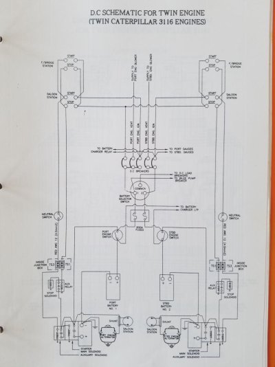
I'm attaching the GB CAT 3116 DC wiring schematic. I can read a basic diagram, but my skills are limited. The alternators and amp gauges are at the bottom of the page. Thanks in advance!

GB CAT 3116 DC Wiring Schematic.jpg
 
Did you raise the engine above idle speed?

I'm going to suggest that the meters shown are not capable of showing a low amperage output. They show 140A-0A- 140A with the needle range of 270o.
The needle at 5- 10A will move very little. THat may have been what you saw.

I also note that the meters will work ONLY with output from the alternator. The meters, even though they are +/- meters, due to the shunt position will only show alternator output.

If the batts. are charged and you start the engine the alternator has very little to do. To boot unless the alternator revs are somewhat above engine idle revs it may not be capable of putting out much amperage. Most alternators need to be run at , at least , two to three times the engine rpm.

Take a look at an alternator output curve chart. Unless the alternator is specifically designed for very low rev. output it may only produce a few amps at engine idle. Typically that type of high output at low revs alternator is not installed except by an owner, either themselves or by a mechanic at the owners request.

To ensure the alternator is run properly the ratio between the crankshaft drive pulley and the alternator driven pulley must be known or estimated. Then the alternator rpm can be calculated and the output chart used.

Next time Shut the charger OFF.

Turn a bunch of stuff on to put a load on the alternators. In fact best if you just start one engine and turn on lights, fans, electronics, if you have an inverter/charger turn it on and use the inverter to boil a kettle but UNLPLUG the boat or turn off the 120V breaker so the charger part cannot operate and then see what the ammeter shows. Raise the engine revs to about 1500 rpm.
Then shut that engine down and start the other and do the same.

If the ammeters do not react, then there may be a problem.

You have enough suggestions about how to check for problems if indeed the ammeters are not working.

Your ammeters are shunt fed. The shunts are right next to the alternators on the dwg.

I will emphasize you must be absolutely positive that the wiring at the shunt itself AND the meter are in fact CLEAN AND TIGHT. The signal produced by a shunt is typically on the order of 50 milliamps at FULL range., less at lower alter. output. If the connections AND crimps are not clean and tight then that signal cannot get through. ALL CONNECTIONS/CRIMPS

My own had that problem when the boat was new to us and taking care of the connections including new terminals on the wires at both ends started my ammeter working.
 
Last edited:
The gauge should read zero with key off or key on stopped. That it does not indicates there is no continuity on one wire between the gauge and shunt, and the gauge is improperly wired. I'm going to jump to the conclusion that it goes to zero when the key is switched on. That would tell me one terminal of the gauge is connected to the shunt and one to ignition. Not shown in the schematic but there should be 2 fuses at each shunt. Check those and check that the gauges are wired as shown, with no other connections to them.

Normal starting uses very little battery capacity. A fully charged battery's demand after normal starting will be low and will diminish further very quickly, not much will show on a 140-0-140 meter. Turning off the battery charger for a time before starting will give you a higher reading.
 
GB. Voltmeter topside, ammeter below.

My GB42 had voltmeters topside and ammeters at the lower station.

That's what I've got on my GB 36, and am wondering what is the point of that. It would help me understand what is for me a difficult system to understand, from those of you with a better understanding of what it is trying to tell me. Great question.
 
It would be helpful if the diagram you provide had more resolution. It appears that you have a two wire alternator with a built in regulator. If that is true they will only charge to about 13.8 volts and will not fully charge your battery system. There are alternators and external regulators that will properly charge your batteries. Balmar makes both alternators and regulators that will properly charge batteries. Wakespeed makes two regulators that control the alternator field current to allow the alternator to charge the batteries up to about 14.7 volts and will drop to about 13.4 volts when the batteries are fully charged. I bought an alternator and Wakespeed regulator for my cat 3208 engine that directly replaced the original alternator. Its a tight installation. "How to Marine", Rob Collins built the alternator and I chose a wakespeed regulator. The cost for both as I recall was less than $700 for a 100 amp small frame alternator last year. You need to have both accurate digital volt meters and amp meters to properly read the battery voltage xx.xx volts and amperage. Blue Seas makes this type of equipment.
 
The ammeter shows battery status and the voltmeter shows alternator status. The voltmeter is preferred to tell at a glance if your charging system is working properly. Judging this from the ammeter is a bit nuanced. For some reason ammeters became the convention early on in automotive and carried over to marine. The ammeter can alert you to a battery with a shorted cell by showing that it is demanding too much for too long while the voltmeter shows normal.

... they will only charge to about 13.8 volts and will not fully charge your battery system.

Regardless of type or configuration, alternators with integral regulators may have settings between 13.8 and 14.4 volts, with 14 being nominal, same for units with preset external regulators.

I do favor two stage charging, but don't have it. My alternator setting is 13.8, charger even lower at 13.6. Many would expect my batteries to suffer some loss of performance, but it is not so. I have Trojan T-105s and this coming will be their tenth season in service. On discharges up to 40% (they don't get any lower as I only use 10-12%/day) the no-load voltage still corresponds almost precisely with the manufacturer's graph, after nine years under the same conditions. This has surprised me going past 7 then 8 years, but the numbers don't lie. It is important that batteries get fully charged after use, and lower voltage takes longer to complete charging, so 13.8 may not be good for everybody. I have a plan, not yet a priority, to install dual regulators for two stage charging controlled from the helm. All but the most sophisticated and expensive 'smart' regulator systems run on elapsed time, they aren't really that smart.
 
That's what I've got on my GB 36, and am wondering what is the point of that. It would help me understand what is for me a difficult system to understand, from those of you with a better understanding of what it is trying to tell me. Great question.

Being a 1972 installation, my GB's lower station ammeters were not the shunt style meaning that heavy gauge cable was run from the alternators to the meters. Running that kind of cable to the upper station would have been silly when voltmeters would require quite a bit smaller wiring. Anyway, I guess GB figured that way you could have both readings, even if they were not co-located.

I changed the ammeters to shunt style later on, but the voltmeters remained as per original.
 
Am I correct in thinking that if I connected my neg bus bar to the load side of a shunt instead of to ground I could use my ammeter as a rough load indicator? Would a 50-0-50 analog give me enough resolution or would I have to go digital?
 

Latest posts

Back
Top Bottom