Isolation Transformer Help

The friendliest place on the web for anyone who enjoys boating.
If you have answers, please help by responding to the unanswered posts.

DegoRed

Veteran Member
Joined
Sep 13, 2019
Messages
88
Location
USA
Vessel Name
Golden Eye
Vessel Make
Burger 52 LRC
Am hoping that some of the guru's who commented in this thread https://www.trawlerforum.com/forums/s3/isolation-transformers-60858.html and this thread https://www.trawlerforum.com/forums/s4/install-isolation-transformer-55099.html can jump in and help.

My base problem is with all the new power pedestals that the marina's are putting in, its making it so I can't hook up shore power. Won't get into the whole 208 vs 240 issues which is also a problem, but right now just need to solve the hooking up to new power pedestal issue.

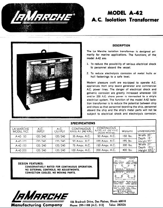
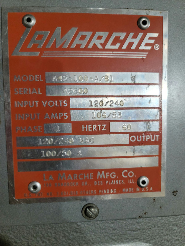
I ALREADY HAVE AN ISOLATION TRANSFORMER installed, it came with the boat from the factory as my boat is 100% aluminum, so it was a must have from day one.

MY theory on why I can't use the new shore power pedestals is due to the way the boat was wired from day one. I know this as I blow or fault the new power pedestal's the very second I plug in either Port or Starboard shore power cord with everything on boat turned off, power selector in OFF position neither Ship nor Shore selected.

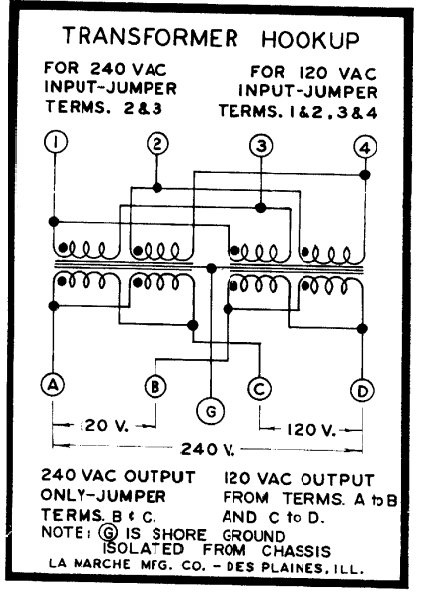
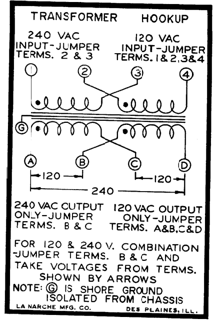
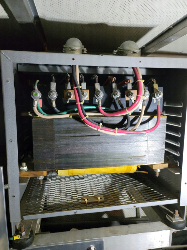
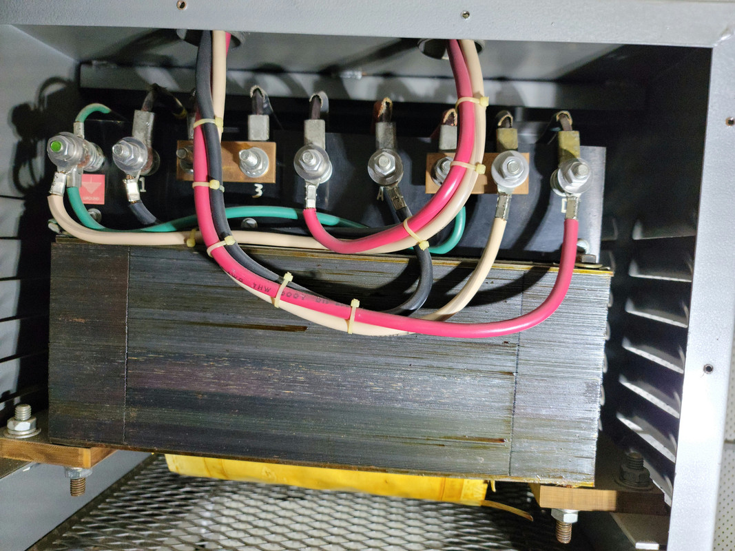
Both shore power cords come directly into the Isolation Transformer prior to going anywhere else. Now I guess it could be the Isolation Transformer is bad, but I am guess its in the way its wired. I took some pics to help, but basically the Ground and White wire are tied via jumper buss bar together. My theory is the new pedestals don't like the ground and the White (Neutral) being tied together, but that is just my theory, has zero issues on older power pedestals only the new ones giving me heartburn.

Am sitting at dock tonight running generator all night since the marina we stopped at only has new pedestals none of the old style. This is 3rd time we have run into this issue in about 10 marina's, but its really a PIA.


20211211-061213.jpg
20211211-061148.jpg
20211212-180215.jpg
20211212-180356.jpg
 
Paul
First the disclaimer... I am NOT a marine electrician and not even a dirt electrician.
Do you have the manual / installation instructions / schematic for the xfrmrs?
While my impression is you are on the right track if the bonded connections you show are the inlet side but no way to tell from the photo.
If you look at Steve D Antonio's article linked in one of the posts... the isolation hook up clearly shows a separate ground and neutral returning to shore. However, on the boat side the xfrmr case ground is bonded to the boat side neutral.
My best recommendation is to get out or find the documents for your xfrmr as a first step. You can then trace out your connections to confirm how yours are wired as a start.
There are some very knowledgeable members here as well as some half baked "experts" (myself included).
Good luck. I'll be following to learn myself as our marina has be completely refurbished including a new electrical supply system. It took the marina a couple seasons to get the bugs worked out and the new system operating properly... some boat issues but also some installation / adjustment issues (some of the new shore breakers are adjustable and require a laptop and trained technician to set them up properly)
 
Won't get into the whole 208 vs 240 issues which is also a problem, but right now just need to solve the hooking up to new power pedestal issue.

I know this as I blow or fault the new power pedestal's the very second I plug in either Port or Starboard shore power cord with everything on boat turned off, power selector in OFF position neither Ship nor Shore selected.

Both shore power cords come directly into the Isolation Transformer prior to going anywhere else.

Does that mean both of your shore power cords are 50A/250V? And you have a choice of one or the other, perhaps to improve access to a given pedestal location or some such?

Or...?

Do you have an inverter installed? I've read that many of the issues with shorepower GFCIs have been caused by the way inverters are wired in...

-Chris
 
Don, do not have any literature at all what so ever from the Iso Transformer, am waiting for them to open up this morning, that is my first call. The Iso Transformer is on their list of discontinued products, so I am worried the manufacture will not have any info either as this transformer was made in 1980, but am going to call anyway, might get lucky.

I did download Steve D Antonio's "Shore Power Transformer" pdf. I am probably above average in my electrical knowledge, I feel as though I don't know much, which leads me to often confuse myself if that makes any sense. That is why I am hopeful that some of the guru's will chime in and help.

In looking at the last Pic posted, there are a total of 9 terminals or studs, going left to right it is as follows:
Ground #1 #2 #3 #4 A B C D

The left power supply coming in goes Black to A, White to C, Red to D
The right power supply coming in goes Back to #1, White to Ground, Red to #4

My suspicion is that 1-4 is the same as A-D and should be wired the same to make the new pedestals happy. Where as right power supply White needs to move to terminal #3 to match left power supply White going to terminal C. Then the Ground wire attached to terminal B needs to be disconnected as I think this is causing the fault, but this is where my electrical knowledge is limited and where I start to doubt myself.
 
Chris, I do have separate Port & Starboard 50Amp power cords, those are the two feeds coming into the top of the Isolation Transformer. Basically the purpose is depending on a Port or Starboard tie at the marina you use one or the other.
 
This is from Steve D Antonio's pdf, and this is what is giving me pause. This is basically what I have.

"For vessels that use a transformer with a 240V primary and a permanently installed shore-power cord-reel system, yet another benefit is available: Standard shore cords used without transformers in split-phase applications have four wires—two hot legs, one neutral leg, and a safety ground. However, because 240V shore-power transformers require no neutral at the primary, this wire can be safely eliminated, making the cord smaller, lighter, and less expensive."
 
I see both a jumper strap from N to G on output side, and a Wht wire with a Grn wire on input side. Thats a problem. And will cause a ground fault trip shoreside
 
Dave, thats my theory as well, btw those are both inputs, no output, but still thats where I see the issue as well. Its just Steve D Antonio pdf stating that I really don't need the White at all that throws a wrench in my thinking.
 
If I read these post correctly, you require both shore power cords to operate? One cord gets phase A 120V and cord 2 gets phase B 120V? And, no switch or overload protection in this primary circuit? If these terminate into the transformer primary winding, what keeps the alternate male shore power inlet safe if only one cord is attached?
Something odd here.

Yes, its true you dont need any Neu connection at. 240V primary attach. For N America.
 
Last edited:
Dave, thats my theory as well, btw those are both inputs, no output, but still thats where I see the issue as well. Its just Steve D Antonio pdf stating that I really don't need the White at all that throws a wrench in my thinking.

You make your own white wire on the output side typically. No need to bring it in from the pedestal.
You say that’s all input wiring? Where’s the output?
It seems very unlikely that you have 8 input terminals unless there is some taps for voltage adjustment. Somewhere, maybe on the back side of a panel there should be a schematic of how the transformer is laid out. Without the schematic we’re all just guessing.
 
If I read these post correctly, you require both shore power cords to operate? One cord gets phase A 120V and cord 2 gets phase B 120V? And, no switch or overload protection in this primary circuit? If these terminate into the transformer primary winding, what keeps the alternate male shore power inlet safe if only one cord is attached?
Something odd here.

Yes, its true you dont need any Neu connection at. 240V primary attach. For N America.

I don’t think he needs both cords to operate. One cord from either input.
 
Chris, I do have separate Port & Starboard 50Amp power cords, those are the two feeds coming into the top of the Isolation Transformer. Basically the purpose is depending on a Port or Starboard tie at the marina you use one or the other.


This doesn't make sense.


The two cables coming into the transformer should be 1) an input which is power coming from shore, and 2) an output which is power feeding the boat.


Your two shore power cables must go to a switch that selected which to use. Only one would (should) be connected to the xfmr input at a time, and the other should be disconnected. Otherwise when you plug in one shore cord, the prongs on the other shore cord would be live. If that's the case, it's incredible dangerous. Do you have some sort of selector switch to pick which shore cord is active? It's also possible that there is an automatic relay.


To understand the transformer wiring, we need to know with certainty which of the cables is coming from shore and which is feeding the boat's power system.
 
I don’t see how you have any galvanic protection with that wiring. It looks like ground and neutral are tied together on what appears to be in and out terminals.
Even if they’re all input terminals, the neutral should not be connected to the ground. That should only happen at the power source on shore.
It’s more likely that we’re looking at input and output wiring, but it’s not clear without the schematic.
 
Pending confirmation that the two cables are input and output, here's what I think we are looking at:


1, 2, 3, 4 are the input side, and A, B, C, D are the output side.


Everything is wired correctly EXCEPT for the input neutral (white). It should not be connected to the ground lug, but instead should be disconnected and capped off.


It's also not clear whether the ground terminal is a chassis ground, or if it's an internal ground shield in the transformer. You could disconnect the wire that's internal to the transformer and meter it to see if it's isolated from the case or not. If it's isolated, then there are further problems. If it's a case ground then all is well, but there isn't an input-side ground shield which I suspect is common for older transformers. Note that the shore power ground is NOT brought to the transformer.

i think you may be right about the terminal layout. the only reason to bring the incoming white wire to the transformer would be to use 120 volt input power in the instance where it's the only thing available. in that case it's probably hooked to the center terminals, not the ground lug. the label does indicate 120/240 input.
 
i think you may be right about the terminal layout. the only reason to bring the incoming white wire to the transformer would be to use 120 volt input power in the instance where it's the only thing available. in that case it's probably hooked to the center terminals, not the ground lug. the label does indicate 120/240 input.


What are the chances of tracing those cables to be 100% certain which is which? I think it matters quite a bit because depending on which is which, your ground bonding is either fine, or requires a bunch more investigation and fixing.


Also, I think it's critical to understand how your two shore power cables are switched to feed the transformer input. I would be really surprised, and quite horrified if they are not switched somehow.
 
*I do have a selector switch to switch from Starboard or Port power feed.
*I have a port side power cable and a starboard side power cable. Either power cable takes a 50amp-240V power feed, they do not combine together.
*On the very first pick, you can see the 2- 90deg connectors that come into the transformer box, on the back of those 90deg they are connected directly to the flexible power cords coming from the cord reels, so basically the opposite end of the cord that plugs into the power pedestal.
*Am sure there is an output on the back, but have not dived into that part yet.
*Spoke to manufacture this morning, they are looking to see if they have any info, but guy sounded doubtful.
 
What are the chances of tracing those cables to be 100% certain which is which? I think it matters quite a bit because depending on which is which, your ground bonding is either fine, or requires a bunch more investigation and fixing.


Also, I think it's critical to understand how your two shore power cables are switched to feed the transformer input. I would be really surprised, and quite horrified if they are not switched somehow.

pretty sure he mentioned a ship/shore selector. but the transformer is fed directly from the inlet plug. (i think that was mentioned too.) doesn't seem like you could have it both ways. there must be an inlet selector to feed the transformer.
if no schematic is available i'd start ringing those out.
actually, i'd ring them out anyway.
 
*I do have a selector switch to switch from Starboard or Port power feed.
*I have a port side power cable and a starboard side power cable. Either power cable takes a 50amp-240V power feed, they do not combine together.
*On the very first pick, you can see the 2- 90deg connectors that come into the transformer box, on the back of those 90deg they are connected directly to the flexible power cords coming from the cord reels, so basically the opposite end of the cord that plugs into the power pedestal.
*Am sure there is an output on the back, but have not dived into that part yet.
*Spoke to manufacture this morning, they are looking to see if they have any info, but guy sounded doubtful.


OK, I remain very confused. I would expect the shore cords to lead to your selector switch, then a single cable leading to the transformer input.


If there is a third cable connected to the transformer, that will be important to know about, and would be yet another surprise.


Any of this can completely change any interpretation we have so far, so it's really important to know with certainty what we are looking at.


Any chance of picture of the selector switch, and any cables going to/from it? Is it a big switch that goes clunk, or a small switch that goes click. Those are scientific terms, of course.
 
The manufacture had a very rough pdf they sent me, converted to jpg and attached.
Screenshot-2021-12-13-110749.png


Screenshot-2021-12-13-110659.png


Screenshot-2021-12-13-110624.png
 
ok it seems like we thought. shore hookup from selector to terminals 1&4 ground to terminal g. 240 only input power, no white wire needed.

output on abcd depending on voltage required.
 
Yes, just went and looked again inside transformer box, think yall were correct. There is just the two lines coming into/from box on top, no others. Its not the shore power cord as I though, it just looks like it as the wire they used has a yellow jacket on it, but its not power cord.

There is no way to cleanly see wires from selector switch in pilothouse down to transformer in engine room, however selector switch only has the Red & Black wires on it, no White.
 
the white is coming from somewhere. the green jumper to terminal b&c needs to come off. (assuming the white is coming from the inlet selector.) your ships ground should be attached to the case. which it looks like it is.
i am assuming the terminal with the green/white is the g terminal on the drawing. you need to isolate it and measure with a meter to be sure there's no connection to the case.
your input would be only on 1&4 ground to terminal g. no other wires attached to the input terminals.
 
So just tape up white incoming wire and zip tie it out of the way?
 
So just tape up white incoming wire and zip tie it out f the way?

no. i should have thought a little more before i posted. i am assuming your white wire on the ground terminal is coming from the shore inlet selector ground terminal. i made the assumption the white was used instead of a green. you need to verify this!
if this is indeed true, simply remove the green jumper. also verify the green attached to the case is the ships ground wire.
 
for clarity, inlet wires red and black to terminals 1&4. inlet ground to terminal g. (transformer shield.) verify that the white wire is inlet ground.
output wiring is red and black to a&d, white to b&c (jumpered with copper bar), green to case.
 
one more thing, maybe someone else can chime in on this, i think you need to connect the output white wire (terminal b&c ) to the case ground. (not terminal g)
 
Here is a pic of the ground wire, it is attached to the stud, then drops down to nut below, maybe wire is 4 inches long.
20211213-132257.jpg
 
So the question is what to do with the White incoming wire? Already removed the green jumper from Ground Stud to terminal C/B
 
Back
Top Bottom