bluewater 40 factory ac wiring

The friendliest place on the web for anyone who enjoys boating.
If you have answers, please help by responding to the unanswered posts.

Bmarler

Guru
Joined
Aug 1, 2021
Messages
1,841
Vessel Name
Rendezvous
Vessel Make
Blue water 40
ok bluewater owners, here's another question.
i'm doing some cleanup on the ac systems wiring on my boat and i'm wondering where the original ac neutral buss is located.
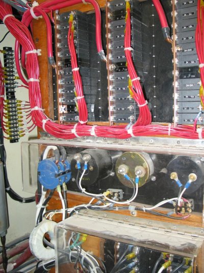
i see some of what appears to be factory terminal strips under the helm station but the wire colors aren't right. i see some of the terminals jumped together, and there's also what appears to be a green bonding wire on some of them. i can see nice bundles from the ac breakers that seem to go down into the wireway that leads to the engine room, but nothing appears to land on a neutral buss with any white colors. i'm thinking the factory may not have used white for the neutral.
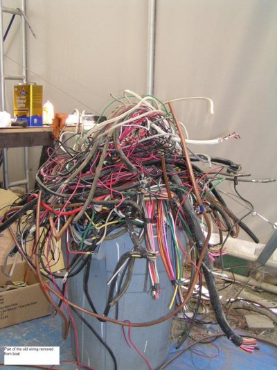
the previous owner did a bunch of wiring and for some reason he made his runs extra long and just rolled up all the excess and left it in a pile under the helm making it even more difficult to trace things out. i will be cleaning that up as well. there must be 50 pounds of boat cable rolled up in there along with a rolled up bunch of 4/0 that comes from the dc busses down below. just crazy.
i've dealt with the "leave it long in case you have to shorten it later" mentality, but this is extreme.
can anyone shed some light on this for me?
 
I think I know your boat, I recall it was early 1970s with a single Bedford. We have a 1979 BW, the wiring was a cluster of original and PO alterations. I spent days chasing it out, ringing wires end to end and relabeling. I have busses in two locations, in the PH cabinet forward and to port (also where the distribution breakers are), and in the ER forward portside bulkhead. I had reversed polarity on some outlets among other horrors. Identifing, labeling, and drawing out a schematic are key to sorting it out. I chose to leave much of the original wiring in place, finding that it was adequately sized and in good physical condition. Leaving enough wire at terminations to allow several future reterminations is good practice, more than that is not.
 
Thank you for that. Yes my boat is a 72 with the single Bedford. My pilot house cabinet has the breakers on the starboard side, and I can’t find any neutral buss up there. I’ll check the engine room port side and see if I can spot it. If all else fails I’ll just start at the shore power inlet and go from there. It’s all going to get opened up anyway.
Originally I was just going to spruce up what was there, but now I’m going in a little deeper.
I’m installing a pair of isolation transformers and checking all the outlet wiring because I have some reverse polarity issues as well as missing grounds in some locations.
It’s going to be a thorough overhaul of the ac system to get it all safe and working properly.
I understand the concept of a service loop in the wiring but this mess is something else.
On the plus side, I’ll get a lot of the wire I need just by shortening the runs in the pilot house cabinet.
Thanks again.
 
If you start at the shore power inlet and main breaker (it should a 2 pole with neutral on one) can you trace the neutral downstream? You might use a meter at that point and ring thru all possible connections, with power off of course.
I'd be looking for any terminal strip that has multiple connections jumpered together regardless of color.
BTW, I've organized a NW Bluewater owners group. We've held several rendezvous' in recent years. Covid has prevented that for a time but I hope to get it restarted. Contact me directly if you like to join: kabystrom@msn.com
 
There’s no breaker by the shore inlet, that’s one of the things I’m fixing. Interestingly enough, there’s an old inlet on the pilot house that’s no longer used, and two in the cockpit. One for the original breaker panel in the PH distribution, and another for an add on panel in the salon. I’ll be adding source selector/circuit breakers at the shore inlets running to the new isolation transformers and then to the distribution panels. Since there doesn’t seem to be any color code I’ll just have to ring everything out to be certain of where everything is connected. I think there’s a strong possibility that the neutrals are shared between the panels, so I’ll most likely have to add new neutral and ground busses. The way the wiring has been handled in the past makes it look like an industrial electrician has been doing the work. Gonna cost a few bucks and take some time to sort it properly.
Hopefully if I can find the original busses I can salvage at least some of the original wiring going to the outlets, but I’m not counting on it.
I’ll send you a direct email regarding the owners group and rendezvous, I’d like to be a part of that.
 
Curious as to why two isolation transformers. We totally re-wired our Bluewater 40 when doing our rebuild-DC, AC, data, Engine wiring. Have one 5kw Acme isolation transformer. Lots of work but, worth it in the long run.
 

Attachments

  • old wiring.jpg
    old wiring.jpg
    163.4 KB · Views: 9
  • agm household bank under floor in msr.jpg
    agm household bank under floor in msr.jpg
    154.7 KB · Views: 8
  • original old wire runs chisled into ceiling.jpg
    original old wire runs chisled into ceiling.jpg
    76.7 KB · Views: 5
  • back of breaker cabinet.jpg
    back of breaker cabinet.jpg
    195.3 KB · Views: 8
  • electric panels and hydronic heater in PH.jpg
    electric panels and hydronic heater in PH.jpg
    126.6 KB · Views: 11
  • electric terminals in PH.JPG
    electric terminals in PH.JPG
    68.6 KB · Views: 8
  • IMG_7873.jpg
    IMG_7873.jpg
    146.1 KB · Views: 6
  • large 12v breakers, starting agm batt, and switches under msr berth.jpg
    large 12v breakers, starting agm batt, and switches under msr berth.jpg
    106.9 KB · Views: 7
That's a good looking installation. I love the trash can full of old wire. My dc primary wiring is all new and sized properly, (if not oversized) but the distribution needs work.
The AC side is a disaster. I need two transformers as there's two shore inlets in the cockpit, and two breaker panels. One in the salon, and one in the pilothouse. I don't want to share busses between the two.
The Genset is 7.5kw and can (mostly) supply both, and when possible I can run two shore cords and not worry about shedding loads if I turn on the microwave while a heater is running.
I bought two new shore/generator circuit breaker/ selectors, and two victron energy auto voltage transformers so I can run 120 or 240 shore power depending on what's available.
It's more than what I really need, but we are aboard a lot in winter and the extra power capacity will be nice.
I wish I could install new DC distribution right now while I have things opened up, but that will have to come later.
 
When we bought Sandpiper, the electrical system was 1/3 by factory and the rest by previous owner. Lots of reverse polarity, missing ground wires, no boxes behind outlets or switches, inadequate wire sizs and minimal breakers.

All the neutrals went to a terminal block on the back side of the steering station, next to the helm pump. I'm not sure If it was factory or PO.

I tried tracing circuits to make a wiring diagram but gave up after spending a day crawling around. I found that all the factory Chinese wire had extra thick insulation which prevented using the proper crimp connector and many spliced "Y" connections leading to dead ends.

I found it easier to remove old wiring and replace.

This was back in the early 2000's when copper was not as expensive as is now and boat wire was reasonable in price.

I’ll just have to see if anything can be salvaged. I can see the original wiring runs are well organized and intact, albeit with no good color code. I can heat shrink new labels on the ends for identification if I decide to leave anything. Lately it’s been tough to get boat cable. Fisheries has been out of stock on popular sizes and port supply price is too high, if they have stock anyway.
I think the heavy insulated original wire will take an uninsulated crimp and solder end with that heat shrink that has the glue inside, should be ok, we’ll see. I need to bounce that off of an aybc certified electrician.
I’m going to touch every connection, I don’t expect it to be quick, just thorough. We have the same polarity and ground issues. It baffles me how badly some people treat these things. Lamp cord. Need I say more?
I have located what I think is an original 120 volt terminal strip under the helm cabinet, but I haven’t isolated it yet to be sure.
It doesn’t have enough wires on it so there must be another neutral buss somewhere. I’m going to pull up all the floors and open the wire way next week. Ugh. At least my wife is also a qualified electrician so she can help too. She’s small enough to get in some pretty tight places too, lucky me.
Hopefully my new steering cable will be in while I have everything opened up, it would be the perfect time to get that taken care of too.
 
Back
Top Bottom