"Now I need to figure out how to add back the 2nd start battery cables and wire it all back the way it should be."
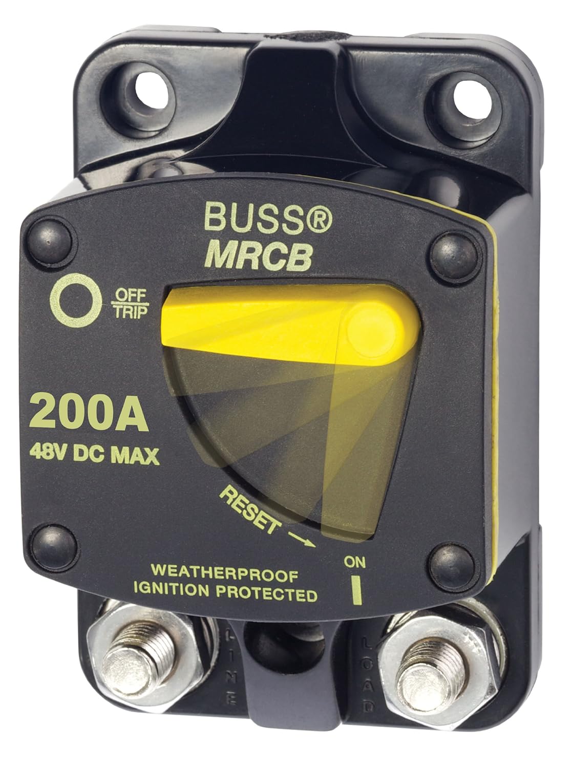
The usually rotary switch to select the start battery should have 2 small alt field disconnect terminals.
If by accident the switch it turned to OFF with the engine operating it will save your alternator.
These have been OTS for half a century + , but many boat builders cant be bothered with having them hooked up.
Battery Switch - Marinco
www.marinco.com/~/media/inRiver/317638-11622.pdf
Alternators with EXTERNAL REGULATOR: Remove regulator
field wire (regulator “F”
terminal) and connect to new wire leading to Guest
battery switch field terminal (either
terminal). Add another wire from other
switch field terminal and connect to regulator “F”
terminal. Use #14 AWG wire for new circuit.


 ,
,