fractalphreak
Senior Member
- Joined
- Jun 23, 2018
- Messages
- 318
- Location
- United States
- Vessel Name
- Northwest Dream
- Vessel Make
- Davis Vashon 42 Trawler (Defever design)
Good weekend all!
I've been stuck doing schoolwork and workwork for the past two weekends, and will be doing schoolwork the rest of this weekend, SOOOOO...to keep from going crazy not out working on or enjoying the boat, I spent some quality time tonight with one of my chartplotters. I realize these are older, but they work and Garmin is still (crossed fingers) putting out legacy GPSMAP updates.
I thought I'd post this because there seems to be a market for the part I bought, so others might have had the same problem.
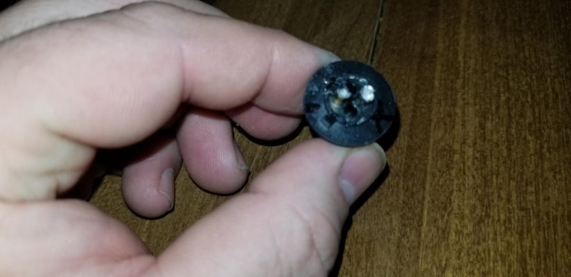
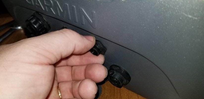
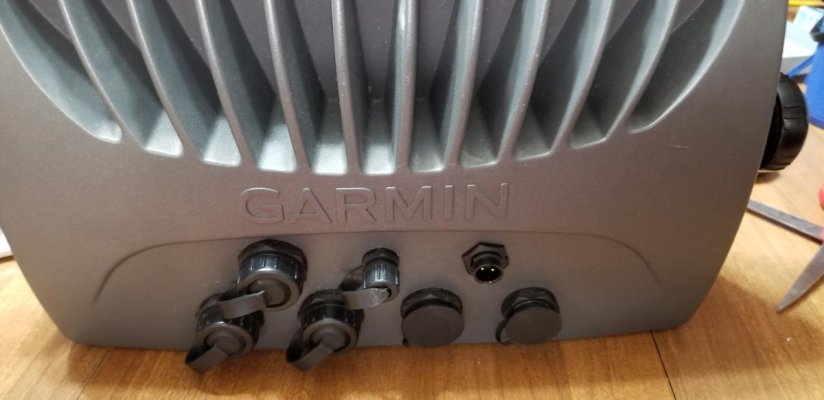
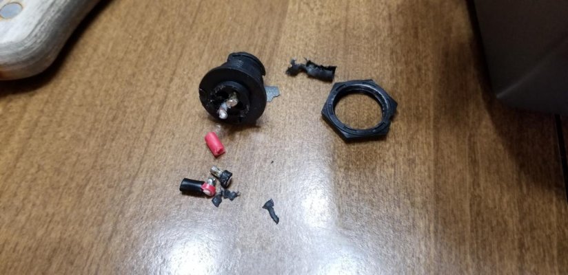
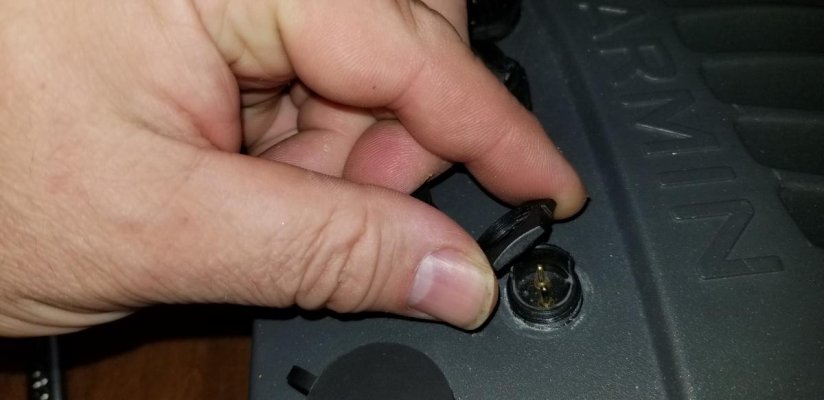
We have two Garmin 4212's, one mounted at the lower helm and the other for the flybridge. Our bridge has a bimini but no enclosure; our PO did and we continue to store the bridge 4212 locked up in the dry salon when the boat is at the marina. At some point, the power connector on the back has gotten broken - the power cord would still plug in but it would work its way loose and then loose power.
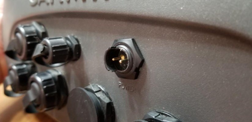
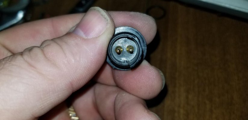
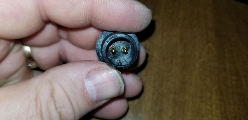
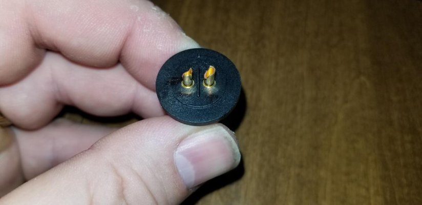
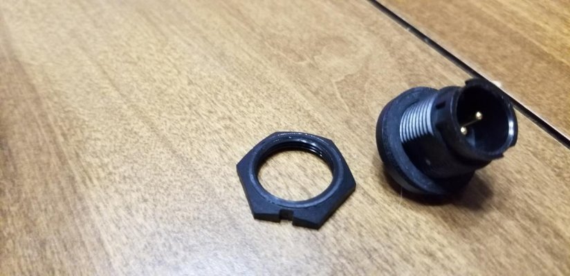
While randomly browsing for 4000-series parts, I found these on ebay. The seller had an offer to do the install for $200. I had never bothered even checking with Garmin on their cost, but bought the part. These units are old and way out of warranty. I worked in electronics assembly in high school, and can solder a bit so I bought it. I later found the same company also sells the connector with a pigtail attached, but that too has to be soldered, this time to a circuit board. I don't think that is any easier or harder.
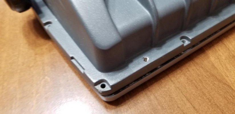
The first step was to remove 16 screws around the case. The case is sealed with a rubber gasket which thankfully stayed in place the entire time on one half of the case and didn't stick to the other side.
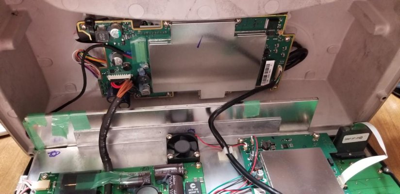
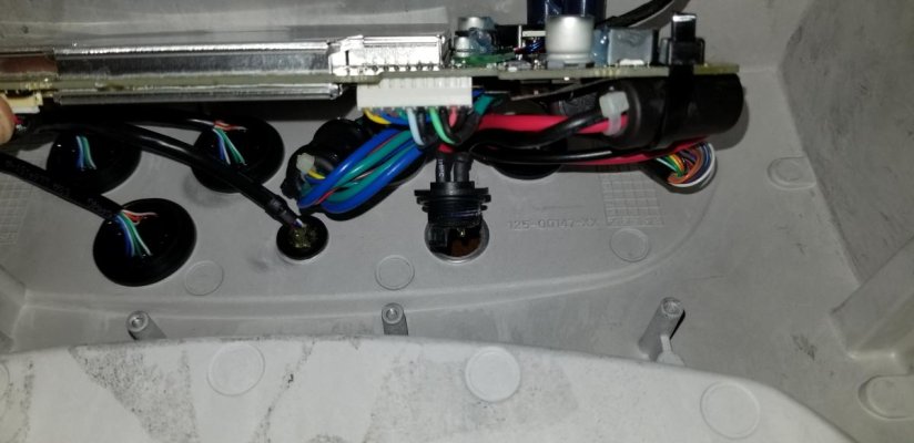
After the screws were out, the case opened up easily. There are a total of three wire harnesses attaching the back of the case to the main body.
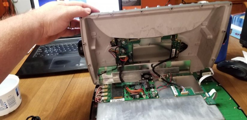
The two with larger wires simply unplug - they don't have captive clips, just a pressure fit. I took photos of them as I removed them, but the connectors only go together one way, and the two harnesses have slightly different connectors so no mixing them up.
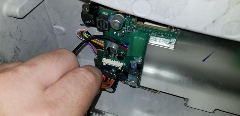
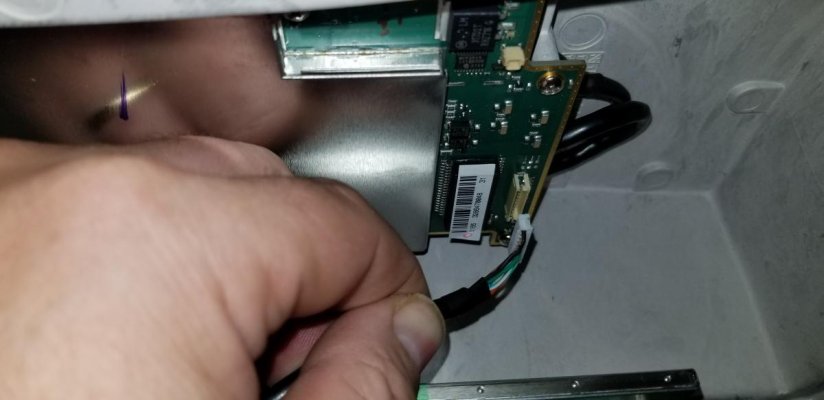
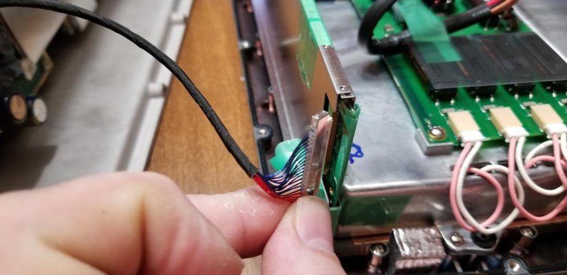
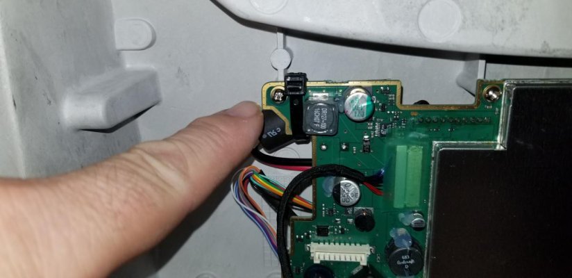
The wire harness on the left of this picture is very thin fragile wires. The connector in this case is also a pressure fit, and very thin. They have secured it with green transparent tape that seems to be scotch-type tape.

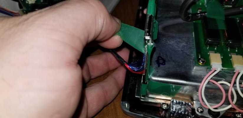
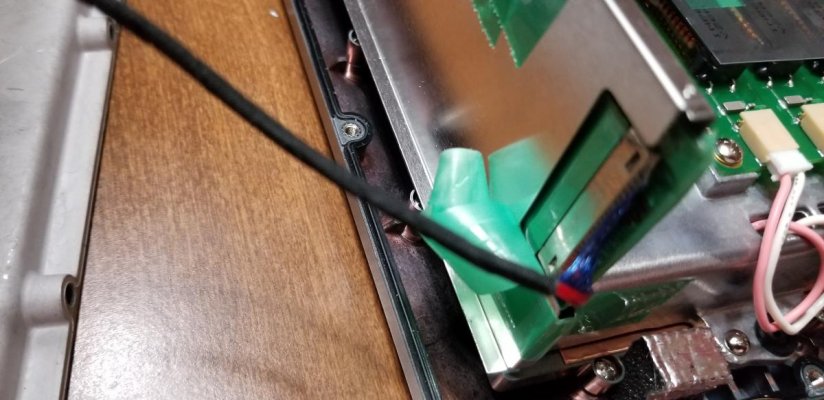
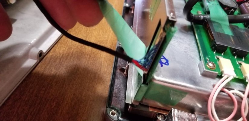
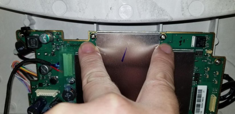
I carefully peeled it back....
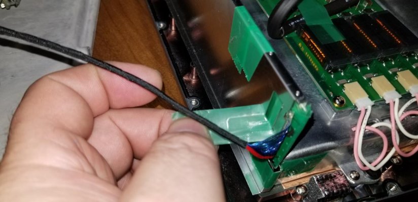
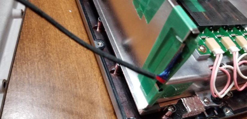
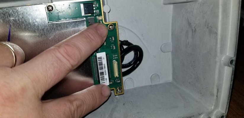
and pulled the connector right out...
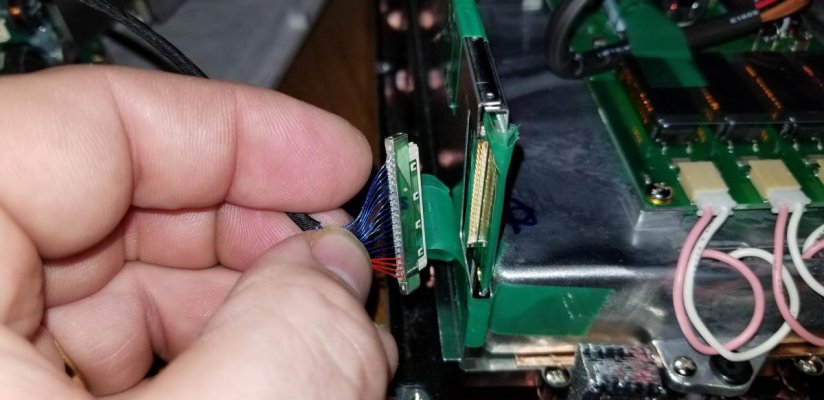
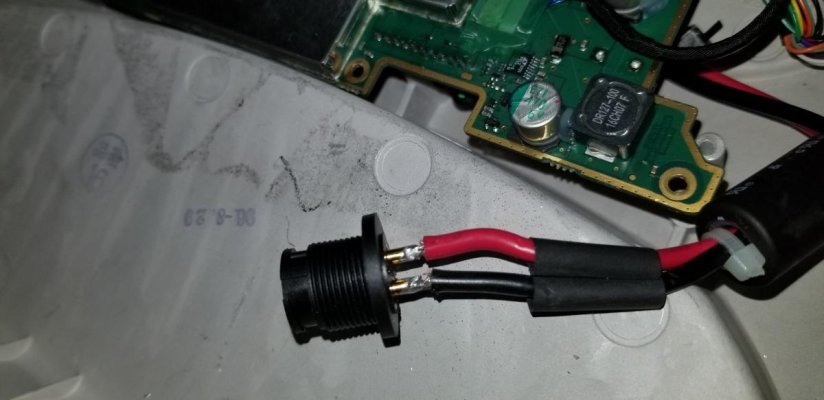
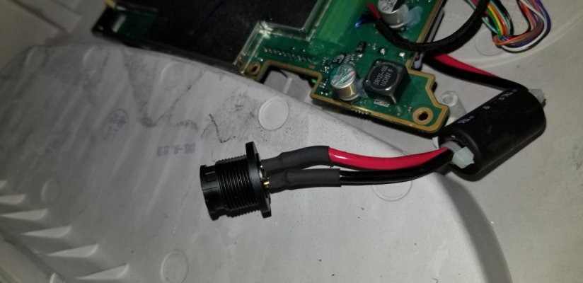
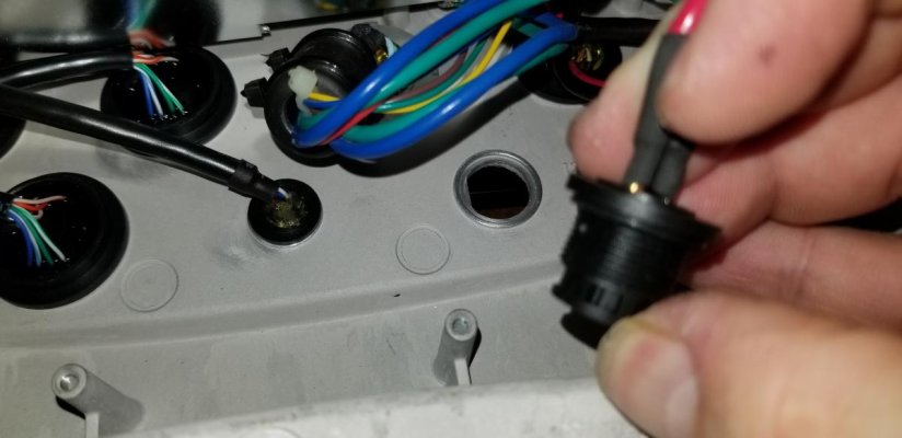
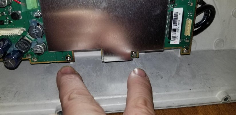
...this separated the two halves of the MPD, allowing me to get to the back half to work on the power connector. More in the next post so I can add pics of that part of the process.
I've been stuck doing schoolwork and workwork for the past two weekends, and will be doing schoolwork the rest of this weekend, SOOOOO...to keep from going crazy not out working on or enjoying the boat, I spent some quality time tonight with one of my chartplotters. I realize these are older, but they work and Garmin is still (crossed fingers) putting out legacy GPSMAP updates.
I thought I'd post this because there seems to be a market for the part I bought, so others might have had the same problem.
We have two Garmin 4212's, one mounted at the lower helm and the other for the flybridge. Our bridge has a bimini but no enclosure; our PO did and we continue to store the bridge 4212 locked up in the dry salon when the boat is at the marina. At some point, the power connector on the back has gotten broken - the power cord would still plug in but it would work its way loose and then loose power.

While randomly browsing for 4000-series parts, I found these on ebay. The seller had an offer to do the install for $200. I had never bothered even checking with Garmin on their cost, but bought the part. These units are old and way out of warranty. I worked in electronics assembly in high school, and can solder a bit so I bought it. I later found the same company also sells the connector with a pigtail attached, but that too has to be soldered, this time to a circuit board. I don't think that is any easier or harder.

The first step was to remove 16 screws around the case. The case is sealed with a rubber gasket which thankfully stayed in place the entire time on one half of the case and didn't stick to the other side.

After the screws were out, the case opened up easily. There are a total of three wire harnesses attaching the back of the case to the main body.

The two with larger wires simply unplug - they don't have captive clips, just a pressure fit. I took photos of them as I removed them, but the connectors only go together one way, and the two harnesses have slightly different connectors so no mixing them up.


The wire harness on the left of this picture is very thin fragile wires. The connector in this case is also a pressure fit, and very thin. They have secured it with green transparent tape that seems to be scotch-type tape.


I carefully peeled it back....

and pulled the connector right out...

...this separated the two halves of the MPD, allowing me to get to the back half to work on the power connector. More in the next post so I can add pics of that part of the process.

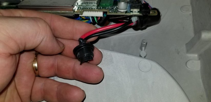
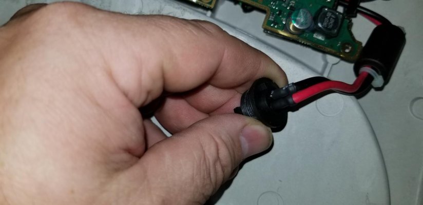
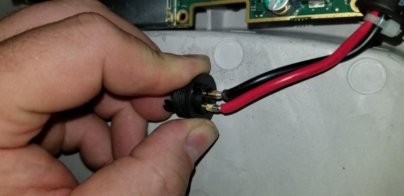
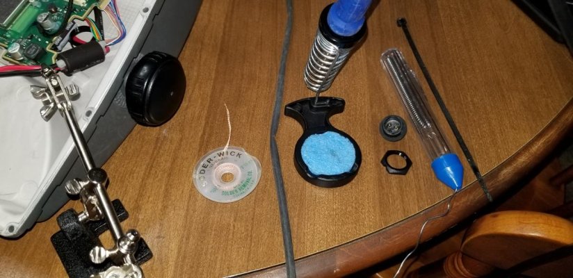
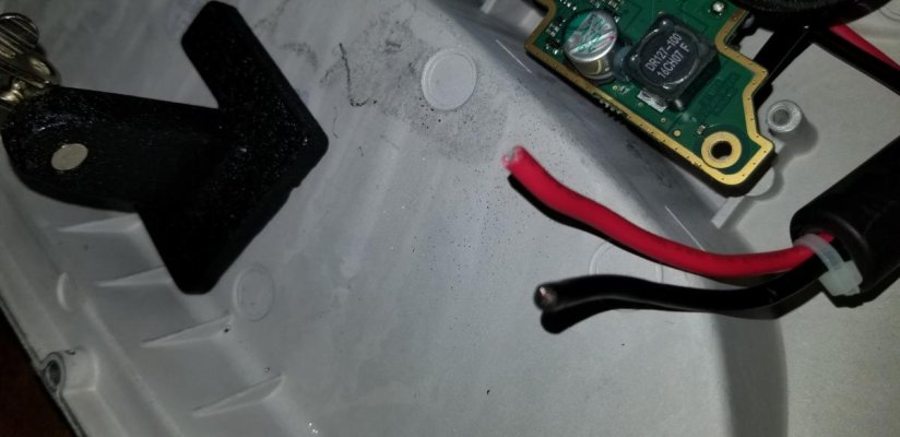
 I took a close look at whether I needed to stop and resource. The Garmin draws 4 amps, and my internal power wires from the plug to the board are 12 awg (measured approx .080). This MFD is mounted on the flybridge and gets its power from a circuit breaker mounted in the overhead right above the lower helm station. Its an approximate 10-12 ft wiring run from the breaker to the MFD, which puts me at a required 16 awg for up to 5 amps at 15 feet. I decided to see what size the wire would have to be to reliably get it inside the tubes; I ended up trimming about 8-10 strands from each wire. Afterwards they measured .070 to .071 and fit the tubes of the connector just fine. There was no part number/marking on the connector, I'm thinking that its a like/same but is made for metric wire - 2.5 mm2 wire is supposed to be .70ish. In the end I decided to stick with my trimmed wires due to them still be so far oversized. I tinned the ends of the wires with solder.