Gordon GB
Veteran Member
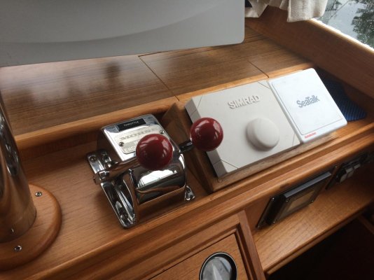
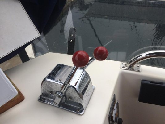
I’ve got a problem with my throttle controls. The pictures show the throttle lever positions at the lower helm and the upper helm. The actual throttle positions on the engines are the same for each engine (similar to the lever positions at the lower helm). The upper helm levers retain their relative positions throughout their range of travel. How can I adjust the levers at the upper helm so that they are more in line at the same RPM?
 The upper controls are not aligned when fully throttled down. When control is disconnected from cables levers align when backed down to lowest position. Upper will not lower rpm below 900. I've tried "lengthening" the upper cable with the end adjustment threads holding the pivot as the upper cable is a push to lower throttle. The lower control actually lowers the rpm lower than idle when fully backed down. What the heck am I overlooking?