Boat Wiring and Onboard Heaters

The friendliest place on the web for anyone who enjoys boating.
If you have answers, please help by responding to the unanswered posts.
Hmm, Ted, water flow. As it is, I have always been suspect of the volume of warter flow. Since purchase five years ago it never seemed all that strong even after have acid-cleaned the innards. I will take a look at the model of pump I have. Perhaps it is underpowered. I will report back. Thank you for your insights.
That may be a function of water flow or design of the unit. My Webasto produces near full output with 40 degree water temperatures. Most reverse cycle home heat pumps and split units produce good heat at or below 40 degrees. My home geothermal will work well down to 20 degrees (antifreeze in loop) although it's never been below 45 yet.

Also there is a noticeable improvement in heating and air conditioning BTU output when I changed water pumps. The output is now about 7 gallons per minute (measured at hull discharge) for each unit (12,000 BTU).

Ted
 
Hmm, Ted, water flow. As it is, I have always been suspect of the volume of warter flow. Since purchase five years ago it never seemed all that strong even after have acid-cleaned the innards. I will take a look at the model of pump I have. Perhaps it is underpowered. I will report back. Thank you for your insights.

Check the hose between the hull valve and the pump. Mine fills up with sea creatures so I have to replace the hose. Cleaning it out is not good enough.
 
Hmm, Ted, water flow. As it is, I have always been suspect of the volume of warter flow. Since purchase five years ago it never seemed all that strong even after have acid-cleaned the innards. I will take a look at the model of pump I have. Perhaps it is underpowered. I will report back. Thank you for your insights.
A relatively simple test you can do if 2 or more of your air conditioners run off the same pump, is to plug one air conditioner's line so that all the water flow goes to the other unit and then measure the heat or cooling output temperature. A simple digital HVAC thermometer (<$20) is a good way to do this. The thermometer is also a great tool for periodically checking performance and discerning early warning signs of potential problems.

Ted
 
Just read the original post again. It was not the outlet that was getting hot, it was the plug. Could just be an undersized crap plug. I’d cut off the end and replace with a plug rated for 15 amps. Also I would stay away from the practice of placing a 20 amp outlet on a 15 amp Circut. The 20 amp outlet is visible and sends a signal that you can insert a 20 amp load. That’s why different loads have different plug designs. The plug tells you the wire/load capacity.
 
Plugging a line, not simple but doable. I may do so as our mid-cabin unit (1 of 3) has never been nearly as good a performer, heating or cooling, as the other two. Plugging that line for now would hardly be a loss as we rarely run it anyway.

The pump is a Dometic. It is supplied by a 3/4 inch raw water hose. Would a one-inch hose make any difference? Since the three output hoses look to be 1/2 ID, I would not think so. Thoughts? I am going to replace the hose anyway. It is only about a 6-foot run.
A relatively simple test you can do if 2 or more of your air conditioners run off the same pump, is to plug one air conditioner's line so that all the water flow goes to the other unit and then measure the heat or cooling output temperature. A simple digital HVAC thermometer (<$20) is a good way to do this. The thermometer is also a great tool for periodically checking performance and discerning early warning signs of potential problems.

Ted
 
I had a lot of 3/4 inch hoses on my AT. When I changed my hull valves from plastic to bronze, I upped them to 1 inch.... on advice. Yes the 1 inch A/C hose, from the hull valve to the strainer, sill gets plugged up with critters but, not as often.
 
Just read the original post again. It was not the outlet that was getting hot, it was the plug. Could just be an undersized crap plug. I’d cut off the end and replace with a plug rated for 15 amps. Also I would stay away from the practice of placing a 20 amp outlet on a 15 amp Circut. The 20 amp outlet is visible and sends a signal that you can insert a 20 amp load. That’s why different loads have different plug designs. The plug tells you the wire/load capacity.


While possible it was only the plug heating up, in my experience and my particular problem it was the cheap outlets heating up and they also heated the plug. If you didn't check the outlet, one might miss it.


If you put in a 20A outlet but keep the 15A CB protecting the circuit...it's no different than having a 30A CB protecting a 30A panel that you plug in too many appliances to and pop it. And that is VERY common.


Sure change it out eventually, but I don't see it as a safety hazard short term until you find a better 15A receptacle or rewire/CB.


People have reported that some manufacturers use identically the same brass guts for the spec grade 20 a and the 15 a receptacle. Only the plastic cover is different. I suspect this is not true on the 59 cent recepts.
 
The pump is a Dometic. It is supplied by a 3/4 inch raw water hose. Would a one-inch hose make any difference? Since the three output hoses look to be 1/2 ID, I would not think so. Thoughts? I am going to replace the hose anyway. It is only about a 6-foot run.

Wow!
What size is the seacock? Most of the pumps that run air conditioners are centrifugal and often magnetic drive. As such, they have modest suction capability and produce minimal output pressure. They do produce good volume. When subject to either suction restriction or output restriction, volume rapidly diminishes. With a smaller diameter and or longer supply hose the pump experiences parasitic line loss. Simply, the walls act as friction to slow the flow down. Curves also add to the restriction. I have a 12' run with some sweep curves between my supply manifold and the pump. The supply hose is 1.5" ID. Too give you some flow perspective, over a 100' run with a 2 psi pressure drop, these sizes can flow the following gallons per minute.

Size----GPM
1/2"----1.25
3/4"----3.5
1"-------8.5
1.25"---14
1.5"-----22

While the numbers are somewhat different in suction, one can clearly see that going from 3/4" to 1" should more than double the flow for the same inches of vacuum. There will only be modest improvement if the seacock is only 3/4". If you have a 1" or larger seacock, I would run that size hose and reduce it as needed at the pump.

On the discharge side I would run 3/4" from the manifold to the AC units. from the pump and the plumbing in the manifold, I would use 1" to reduce head pressure caused by parasitic line loss.

Before you embark on this project, see if you can identify the pump manufacturer and model and post it here. Most offer flow chart graphs based on head pressure and will have minimum pipe size recommendations.

Ted
 
Used to be reverse cycle units air or water stopped when the air or water got to near freezing.

The modern mini splits solve this problem and can produce heat even at -20.

There computers know when the ice forms , they flip the coolant passages and by stealing a bit of heat from the interior can de ice the unitbrapidly.

At that point the unit reverses the valves and resumes heating.

The only complaint is the unit will go to max heat for a min or two to make up for the stolen heat , and some folks can hear rhe fan speed up.

A boat reverse cycle unit will usually quit till the water warms up , and may switch over to a wire heating element , like the one in a toaster.

With a limited electric supply a stand alone resistance heater in the cabin is usually more efficient.

The higher buck ceramic units have a nice feature , when on they will run at 500-600W at all times , only adding the 1000W heat as the thermostat demands.

The cabin temp is more constant.
 
Last edited:
My 40 year old boat had hardwired bulkhead mounted resistance heaters. Almost burnt me down one morning. So those old wires need to be opened up and checked. Also I would never leave it on when away from the boat. But that’s poor tech anyway. Nowadays I’d go with the oil filled units anyway.
 
Electric wire and circurty on a boat surely can be problematic. I wish all the best luck in having correct combination of wire, outlets, breakers and appliances.

Question:

I have opportunity to purchase the following... what do you feel regarding gauge, length and price? Seems good to me... but??

"50' 12 AWG Tinned Duplex 12/2 Red & Black Sheathed Marine Wire - $50"

Thanks, Art
 
Chances are your house has 100 amp service so you can run LOTS of stuff.
50amp boat... you can run house-hold heaters plus.
30amp boat... watch the amp meter.
 
Chances are your house has 100 amp service so you can run LOTS of stuff.
50amp boat... you can run house-hold heaters plus.
30amp boat... watch the amp meter.

Boy O' Boy - Good Advice!!

Due to a decade ago [Christmas lights etc...] over amped near meltdown [main breaker somewhat melted rather than to correctly immediately shut off] - - - > Do I ever watch the amp meter on our 30 amp Tolly.

Since there after installing a new main breaker; I make sure to not let our amp meter register get up to 25 for but for brief seconds. 20 or below is the level I will allow for a few minutes. With careful appliance management the meter can generally stay reading in 15 area. I keep it at 10 +/- for any long durations. :thumb:
 
Actually, as usual..... it depends....


A 50A service is usually difficult to find on East Coast docks anymore. They are mostly 125/250V 50A receptacles or you might have a single or double 30A. Sure some boats still have 50A service but few I know of.


If you are lucky enough to have a 125/250V 50A service on your boat, my research shows it can provide nearly 100A of 125V to appliances. That's why I upgraded to a 125/250V 50A service as a liveaboard.


I have been told you don't get the full 100A...but I believe it is still more than 2-30A. So I feel better running pretty much whatever I want on my 40 footer. Space heaters, oven, water heater, etc...etc... RARELY is load shedding necessary.


The biggest concern would be a hair dryer...but in those spaces you can turn off the other kind of heat if necessary.


There are 2-50A legs
 
Last edited:
My boat is a 30amp boat and I am thinking of putting an Amp meter in the galley area.
Maybe 2 years ago, I replaced the 2 amp circuit breakers closest the shore power cables and then, replaced the shore-power breakers on the main panel.
NOW, I am trying to figure out why sometimes the panel shore-power breaker opens and sometimes the breaker between the shore-power plug and the panel.


Maybe air cond starting loads? If the water heater cycles on there might not be enough reserve power to accommodate.
 
Maybe air cond starting loads? If the water heater cycles on there might not be enough reserve power to accommodate.

AC is on separate 30amp leg.
I will have to watch and see what cycled on to get a hint on why one set of breakers trip and not the other set.
Thanks.
 
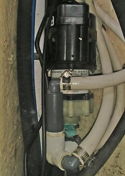
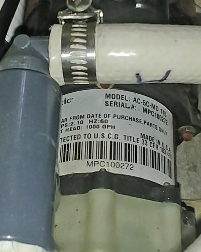
Ted. Here is the update. The pump is a Dometic/March Model AC-5C-MD nominally rated at 17 GPM/1000 GPH. It feeds three units through 5/8 ID hoses. The raw water supply hose is 3/4. It has one sharp 90-degree sweep and one gradual 90-degree sweep to the sea-cock over about 8 feet of hose. The sea-cock and the pump can be changed to a 1" output.


ac2.jpg

ac1.jpg


Wow!
What size is the seacock? Most of the pumps that run air conditioners are centrifugal and often magnetic drive. As such, they have modest suction capability and produce minimal output pressure. They do produce good volume. When subject to either suction restriction or output restriction, volume rapidly diminishes. With a smaller diameter and or longer supply hose the pump experiences parasitic line loss. Simply, the walls act as friction to slow the flow down. Curves also add to the restriction. I have a 12' run with some sweep curves between my supply manifold and the pump. The supply hose is 1.5" ID. Too give you some flow perspective, over a 100' run with a 2 psi pressure drop, these sizes can flow the following gallons per minute.

Size----GPM
1/2"----1.25
3/4"----3.5
1"-------8.5
1.25"---14
1.5"-----22

While the numbers are somewhat different in suction, one can clearly see that going from 3/4" to 1" should more than double the flow for the same inches of vacuum. There will only be modest improvement if the seacock is only 3/4". If you have a 1" or larger seacock, I would run that size hose and reduce it as needed at the pump.

On the discharge side I would run 3/4" from the manifold to the AC units. from the pump and the plumbing in the manifold, I would use 1" to reduce head pressure caused by parasitic line loss.

Before you embark on this project, see if you can identify the pump manufacturer and model and post it here. Most offer flow chart graphs based on head pressure and will have minimum pipe size recommendations.

Ted
 
If the pump is below water level, I’d put two hose clamps on all underwater fittings.
 
Ted. Here is the update. The pump is a Dometic/March Model AC-5C-MD nominally rated at 17 GPM/1000 GPH. It feeds three units through 5/8 ID hoses. The raw water supply hose is 3/4. It has one sharp 90-degree sweep and one gradual 90-degree sweep to the sea-cock over about 8 feet of hose. The sea-cock and the pump can be changed to a 1" output.
Ok, this will be easy as I was using this same pump till October. The below link will give you the March spec sheet and flow graph. The curve line on the graph you want to use is AC-5-MD 60HZ.

https://www.defender.com/pdf/502649_March.pdf

From the spec sheet, the inlet is 1". So 3/4" hose isn't doing you any favors. While the outlet is only 1/2", boosting the size to 1" for the manifold will have benefit for reducing frictional line loss. 3/4" hose from the manifold to the AC units should be fine. If you have a run from the manifold to one of the units that is >25', I would do it in 1" and reduce it going into the unit.

To figure head loss, start with the highest water point at the highest AC unit, and guess / measure that point to sea level. On my boat, the pilot house unit is approximately 8' above sea level. So the best I could hope for would be 14 GPM with that pump. That number doesn't take into account frictional line loss. If you have the AC manual, they usually specify a minimum GPM flow measured at the hull discharge. My Webasto 12,000 BTU unit has a minimum requirement of 4 GPM and 5.25 GPM is recommended. So, with 3 units the minimum is 12, recommend is 15.75, and the pump after static head pressure can best case produce 14 GPM. Inspite of my best plumbing practices, I couldn't get above 3 GPM at the stateroom unit which was >25' away from the pump. Finally conceded defeat; switched pumps which included a larger supply hose; and now have >6 GPM at the stateroom unit discharge. :thumb:

Before you start the process, if practical, measure the discharge for each unit with a 5 gallon bucket and a timer. Always good to have a reference point to start with.

Ted
 
Last edited:
Check all wiring if you are worried

A friend's boat caught on fire from his wife's hairdryer, in Mexico at a plush marina. He asked me to take a look at it. I didn't find the "smoking gun" but I strongly suspect it was from a loose connection somewhere. It fried his AC master breaker, as in open flames fried. A long steady fairly high current will not always trip the breaker but may overheat it or the wiring. An electrical cabin heater is just that type of situation. Check all your wiring, terminals, and connections. Of course, wires should be properly sized, etc.
 
We lived aboard Sandpiper for two winters while building our current house.

Sandpiper has no built in heat.

Our marina at the time had unmetered AC !!!!!!!!!!

I installed a second shore power inlet, split the AC panel and ran two 30 amp cords to shore. Bought 5 Caframo True North heaters and ran them at 600 watts. Installed 20 amp dedicated heater outlets with 12 ga wiring and a 20 amp breaker

Kept the boat real warm. Opened windows for temperature control.

Comes in handy now when we boat in winter and a second shore power outlet is available.


So YOU are the reason its now metered!!!:banghead:
 
Replace the receptacles every 20 years. Don't use the backstab feature. And, if you don't have a good feel for torque, use an instrument. I just finished replacing all the 1988 recepts in my house, and saw a number of issues. A boat doesn't have that many recepts to be a $ issue, and the ones that do exist may get heavy use along with salted atmosphere.
I don't know if this is a rule, but I would not put any stranded wire directly under a screw head. Use devices that clamp the wire end. Also, use devices that are "marine" rated, or at least "WR" (weather resistant). The yokes will be made of a corrosion resistant material.

Some good advice here, and the stranded wire issue is worth expanding upon. It is a violation of ABYC standards for any screw to bear directly on any wire. Typically, in shore-side applications the wiring is solid, which works well under the head of a screw, however, solid wiring is prohibited in marine applications, as are direct-bearing terminals. Stranded wires should either be terminated with a solderless terminal, or captured in a non-direct bearing screw clamp.

On the subject of heaters, this issue was driven home for me as a result of two fatalities caused by a heater, being used on a boat in Deltaville, VA, minutes from my home, a number of years ago. It was fall, chilly, old boat, father and daughter sleeping aboard.

I find that marginal wiring can work fine for years without the operator having a clue there is an issue lurking. However, heavy loads like heaters, hair dryers, and microwave ovens place an especially high load on inferior wiring, which exposes its faults. My advice is to inspect the back of any receptacle in which you intend to use one of these high current devices. Look for loose wiring, undersized wiring, discolored screws or plastic, and any evidence of overheating. If you find faults, then it makes sense to check all the receptacles.

As an aside, all receptacles must be installed inside enclosures; this is a violation I encounter on an all too frequent basis, on new and used vessels, just a few weeks ago I came across this on a new, multi-million dollar vessel, both inside bulkheads and under counter and vanity tops, where they could easily be touched by someone reaching under those areas. This is both a fire and electrocution hazard. A few years ago I encountered just such a violation, with the added feature of a small pile of saw dust piled on top of the exposed receptacle.
 
All you need to check your loading is a voltmeter. Meter the shore power receptacle to determine the baseline. Now measure the voltage drawn by your boat without heaters or ac. Now start plugging in your heaters. As soon as the boat voltage drops below the number you saw on the dock, that’s it. You have reached your limit. You can test this further by plugging in another piece of equipment and the voltage will now be around 100 volts. Now you are at high risk of a failure/fire. Remember to leave a buffer in case your bilge pumps are needed as they can push the voltage down too.

Next time you get to your boat, before you do anything else, check the temperature of the dock plug. If its warm you are overloading.
 
Be careful with these $25 heaters. Their manufacturing cost in China is probably around $5-10. To get there every single item in it has been relentlessly scrutinized to save the last cent. Every bearing, every piece of wire, every switch, every protection feature,... Don't leave them on unattended.

The sad reality is that many electrical products from China have really crappy wire and plugs. Many of the small electric heaters when plugged in and on high, will have quite warm cords and plugs. Can't imagine going to sleep with a power cord so close to the failure threshold.

Ted
 
All you need to check your loading is a voltmeter. Meter the shore power receptacle to determine the baseline. Now measure the voltage drawn by your boat without heaters or ac. Now start plugging in your heaters. As soon as the boat voltage drops below the number you saw on the dock, that’s it. You have reached your limit. You can test this further by plugging in another piece of equipment and the voltage will now be around 100 volts. Now you are at high risk of a failure/fire. Remember to leave a buffer in case your bilge pumps are needed as they can push the voltage down too.

Next time you get to your boat, before you do anything else, check the temperature of the dock plug. If its warm you are overloading.


Yes. I recall doing this experiment to my parents house with a space heater. Measuring voltage drop with a meter. I was 14y/o.
 
Last edited:
I live on my boats. One of the first things I do with a new to me boat is replace the shore receptacle and the wiring to the master panel. In every case I have found the wiring undersized for constant loads pulled during winter. Next, I check the wiring to any electrical heaters. Often I find the wiring only adequate, more often I find corrosion or connection issues.

The next thing I do is a bit complicated for the average person but quite simple for an electrician. I run continuity and resistance checks on all my circuits. This quickly tells me were all the bad connections and/or corrosion issues are.

Last, I don’t believe in using plug in heaters to heat a boat. Heaters should be built in and have their own circuit. Temporary heat sources can be plug in.
 
Back
Top Bottom