I'm not super familiar with the VDO units, in particular. So, I guess I'm waiting to learn what model it is so that I can look up the wiring diagram.
But, something here doesn't strike me as what I'd expect. My impression of most of these rudder units is that the sender, itself, is a variable resistor, changing resistance with position. At the middle position, i.e. neutral rudder, it be at half of its range.
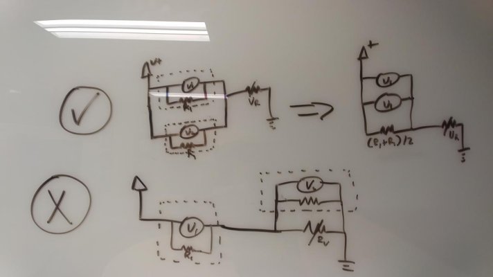
And that the gauge is placed in series with the variable resistor and contains either an ammeter or a voltmeter in parallel with a resistor of known value serving as a voltage divider.
So, if we have a single station sender, the resistance range is X to Y ohms. And, if we have a dual station sender, it is 2X to 2Y ohms. This way the same gauges can be used even though the voltage or current will be divided.
In other words, I don't think that one rudder direction is indicated by current going one way and the other rudder direction is indicated by the current going the other way. I could design such a circuit. And, it wouldn't be super complicated. But, it would be more complicated. And, I'm not sure that I see the gain. More parts and cost are the things I immediately see.
And, the wiring I've always seen on these things wouldn't necessarily work for something more complicated. It has always had + and - going to a backlight on each gauge, and + going to each gauge's meter. Then - from each gauge's meter going to the sender, and from there to ground. I'd expect, minimally, a 3rd wire on the sender for a more complex design, though this isnt necessarily the case.
It almost sounds to me like something is hooked up really weird in the circuit, such as one of the gauges being in parallel with the sender and the other in series with the sender, or something. Then one would move left as the other moved right.
I'd suggest checking that wiring again. I suspect each gauge should be getting independent connections to power + and - as well as the sender.
So, ignoring the light for a moment, if you put your meter on + on each gauge, I think you should be seeing 13V on each. And, if you put your meter on -/gnd on each gauge, I think you should be seeing 0V and continuity with ground (with circuit power off to protect meter). And, also, with circuit power off, measuring from sender to ground at each gauge you should see the same resistance at each gauge, even as the rudder is moved from one stop to another. If you don't see this, the problem is the wiring, not a gauge or the sender.
And, I don't think it is going to be as simple as flipping the plus and minus wires.
But, again, I could be totally wrong about how your system works. I don't know that I've ever seen or touched one and haven't seen a wiring diagram for it, etc. I am totally guessing.