Weird Battery Selector Switch

The friendliest place on the web for anyone who enjoys boating.
If you have answers, please help by responding to the unanswered posts.

SailorGoneBad

Veteran Member
Joined
Nov 4, 2018
Messages
58
Location
US
Vessel Name
Sea Turtle
Vessel Make
Grand Banks 32
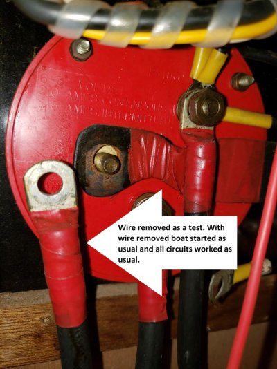
This is the battery selector switch on my 1979 Grand Banks. It is probably original and it works fine. I am getting ready to upgrade the battery configuration and need to understand one thing:

Why is there a cable from the common terminal on the switch to the engine block? Does it need to be there?

Note: Feed from alternator originally went through a couple of diodes so it could charge both batteries. At some point a PO removed the diodes and disconnected the feed to battery 2. Alternator now only charges battery 2 if selector is set to "ALL"

Thanks,
 

Attachments

  • switch.jpg
    switch.jpg
    107.6 KB · Views: 56
  • switch back.jpg
    switch back.jpg
    181.1 KB · Views: 63
Have you put a volt meter on those terminals? "goes to engine block" would suggest it is a negative as the batteries negative should also go to engine block. That post is the output line of either 1 or 2, or both if set to all.
 
Note: Feed from alternator originally went through a couple of diodes so it could charge both batteries. At some point a PO removed the diodes and disconnected the feed to battery 2. Alternator now only charges battery 2 if selector is set to "ALL"


In general I think it is better if the battery selection switch determines where loads will be directed rather than where charge current is going to be directed.
 
In general I think it is better if the battery selection switch determines where loads will be directed rather than where charge current is going to be directed.

That's very true, Dave. I'm a strong proponent of that with the alternator/genset/solar charge going directly to the properly fused battery. But it often takes a whole big cable rewire to make that happen. I tackled it with the conversion from 3 8D batteries to 6 GCs so I was already crimping big cable.

It's also the way airplanes (and my brain) are wired. It's nice to have total control of either the charge side or the load side or a combination of both, as the conditions warrant.
 
Here are my observations. Black wire with red heat shrink. This is so totally unprofessional that i’m Scared of the whole thing. Black wire says (-) or common or ground. Yes you can control things by switching the negatives but I think it’s a much more dangerous way to do things. Are there similar switches for the positive side?

I think you might be best served hiring a professional to walk you through your boats electrical system.
 
My plan is to move the alternator input to a buss bar near battery bank 2 (house) and then connect Battery 1 to Battery 2 (starter) with a Blue Sea Systems SI-ACR Automatic Charging Relay with Start Isolation.

Before doing that I was trying to understand the current configuration and came across this unexpected battery cable connected to the common post of the battery selector switch. It is difficult to trace the battery cables because of access. However, I can trace the battery 1 & 2 cables to their respective batteries (with difficulty). I can trace the positive cable from the starter battery to the starter solenoid (it does not come from the selector switch).

The battery cable to the common post on the selector switch is harder to trace but seems to be one of three battery cables that end up at the engine block. The three cables are:

1) Battery Cable from negative post on generator connects near the transmission.
2) Battery cable from negative post of starter battery to negative side of starter.
3) Battery cable to engine block slightly aft of starter (This is the one that appears to come from the common post of the battery switch.


I am going to disconnect this battery cable at the selector switch and see what happens. While I am at it I will also to a put a multi-meter on it and test for continuity.
 
Back in the day wires only came in one color. All the original wiring in this boat (both DC and 120VAC) is black. Earlier this year I replaced all of the original 120VAC system and moved it out of the cabinet that houses the DC panel. This is, I think, much safer and easier to look at. I am now starting on reworking the DC system starting with the batteries.
 
I disconnected the mystery cable to the common post on the selector switch. Starter still works, boats starts and all circuits worked as before. I still can't figure out why it is there.
 

Attachments

  • wire off.jpg
    wire off.jpg
    130.4 KB · Views: 50
Windlass it is.

That makes much more sense. The mystery wire goes to the anchor locker for a future windlass. (I confirmed with a continuity test.)

For 40 years it has been waiting for someone to install a windlass. Seems kinda funky to leave a hot wire open in the bottom of a anchor locker so I am going to leave it disconnected at the selector switch.

The wire that starts at the engine block goes to the negative buss bar (that also makes more sense)

Thanks for your help.
 

Attachments

  • windlass.jpg
    windlass.jpg
    197.4 KB · Views: 35
Back
Top Bottom