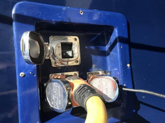
OK, I guess my idea of customer ready isn't.

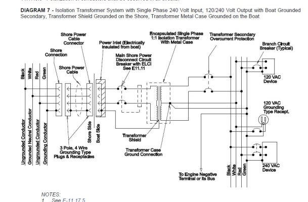
A "line tap" or "boost" offers the ability to vary the transformer primary to secondary ratio. That is, you can accommodate a 208Volt dock and get 240 and 120 to the boat. Important to avoid hot running motors and other mayhem.
The 120 V only boaters will not need a line tap.
The 240 V only (euro boats) and 240/120 V boaters will, depending on the horribleness of the dock electrical design, enjoy the line tap feature to bring up the High voltage about 10%. If you run around lots of places outside of N. America, make sure the transformer you pick is 50 and 60Hz rated.
"Surge" in this context, is a short term transient caused by lightning. These can range up to 4000 volts in my test world. If this pulse exists on both Line and Neutral verses EARTH, we call that "common mode". If, OTOH, you get the pulse BETWEEN Line and Neutral, we call that "differential mode". The iso transformer virtually eliminates the CM pulse, but will (mostly) allow the DM pulse to get thru. A common MOV surge suppressor helps a lot here, and will be installed after the iso transformer for best effect.
Leakage currents, dock GFCI, ELCB's etc and dock swimmer issues. They won't come from a boat with an iso transformer. Nor will an ISO transformer equipped boat trip out a leakage current device upstream at the dock due to any onboard appliance issue. However, a dock plug/socket issue, cord insulation issue, or even a boat shore power plug/socket issue could trip out an upstream leakage current device, even with an Iso transformer.
Yes, this iron/copper iso transformer is heavy, needs careful mounting, but is otherwise pretty bulletproof. NOT using a iso transformer is a "trust me" concept. It usually works, until it doesn't.


 . (Requested by someone who spent a career helping engineers become comprehensible to “normals.”)