House to Start Bank Cross-Feed Question

The friendliest place on the web for anyone who enjoys boating.
If you have answers, please help by responding to the unanswered posts.

Wil

Senior Member
Joined
Jul 8, 2013
Messages
187
Location
US
Vessel Name
Gone Walkabout
Vessel Make
1999 KadeyKrogen 39
In this wiring diagram, all of it, except the House Bank and its positive and negative busses, is Starting Bank wiring. The basic concept is to have a dedicated charge circuit for my 200A isolated ground alternator feeding the 900Ah House Bank using 4/0 cable for both positive and negative sides (with no battery switches in between). Then a cross-feed from House to Start Bank again using 4/0 cable for positive and negative sides, with a Blue Sea 500A Automatic Charge Relay (ACR) to connect the positive x-feed when charging voltage is present. The ACR has three separate operational states via a remote switch: Connected, Disconnected, or Auto (used for sensing charge voltage to auto-connect House to Start bank). There is also a manual switch on the unit itself.

By substituting a 500A Off/Both/1/2 battery switch for the simple #1 Start Battery On/Off switch (as was originally intended), one gains the ability to use either the House (position 1) or Start Bank (position 2) as the power source for the Start Bank loads, or combine (position Both) the banks when using the ACR to charge the Start Bank. The switch can be left on Both all the time when the ACR is in Auto mode—the banks will only combine when charging voltage is present. Another example, to use the House Bank only for the Start loads, put the switch on position 1. Position 2 for just the Start Bank to Start loads.

The Start/House Bank's negative busses combine at the engine block (e.g., starter housing mounting bolt) with 4/0 cable.
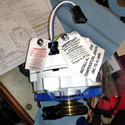
The 200A alternator should have dedicated positive and negative 4/0 cables.
The cross-feed is 4/0 cable to support Start loads when using House Bank.
The 'S-P Contactor' is the series-parallel contactor that puts the two Start batteries in series or parallel configuration for either bow thruster operation or charging both batteries at 12v, respectively.

Question: If the House & Start Bank negative busses are tied together at the engine block (e.g., starter housing mounting bolt) with 4/0 cable, can I just run a 4/0 cable from the alternator isolated ground to the same starter housing mounting bolt(s)? Ground loops?

Question: Does the wiring diagram look functional? Constructive criticism welcome...
 

Attachments

  • House-Start Bank with CrossFeed.pdf
    184.3 KB · Views: 163
Last edited by a moderator:
Wil,
I'm usually pretty good at boat wiring. This looks somewhat convoluted. The more complex it is, the greater the number of failure points. I'm seeing things like an SSB that may or may not have a fuse (no amp rating) that seems connected to a 400 amp circuit. Don't understand why that's not coming off the DC panel? When you say "isolated ground alternator ", are you referring to the negative terminal (as an alternator has no ground) and why is it important not to tie it to the boat's bonding system?

Ted
 
Unlike Ted, I'm NOT good at interpreting schematics.


It looks to me as if the 1/2/Both switch will allow you to isolate the start bank for starting the engines. However, I don't think it will allow you to isolate the house bank to start the engines. The reason being that the ACR won't connect the house bank to the 1/2/Both switch unless there is a charging source to the battery (ie the voltage the relay reads is above its threshold).


So if for some reason you needed/wanted to start the engine with the house bank, you would need to switch the 1/2/Both switch to #1 (taking the start bank offline) but you would also have to switch the ACR closed manually.


In this way, I'm not sure I know what the addition of the 1/2/Both switch gives you? Why not just use an on/off switch in the start battery curcuit? With that in the On position, both banks will be combined when there is a charging source. If you want to start with the house bank and isolate the start bank, you manually close the ARC relay and turn the start bank Off. During normal operation, you would be starting with the start bank only.


I'm sure I am missing something....
 
Will, I have a couple of questions about the design: The series/Parallel contactor is it designed to handle the 12 volt starter current? All of them I've seen are designed to handle the current at 24 volts and the contacts are sized for that current load. another question is it seems possible to have the switch in a position that the starter bank would not receive any charging current. I also would question why have fuses in a starter circuit. it seems to me any possible point of failure in the stater circuit could be problematic.
 
Ted, the diagram and my (over) explaining maybe make it look convoluted? It is basically just a house bank that runs typical house stuff (fridge, lights, etc.) and a start bank that runs the windlass, bow thruster, and main & generator starter motors.

There is a cross-feed from house to start bank that automates (the ACR) what would otherwise 'normally' be a manual selector switch that puts the alternator output to either house, start, or both banks. My system has no battery switches between alternator and house bank, so alternator can never be 'blown up'. The ACR just charges the start bank when charging voltage is present. Don't have to remember to switch alternator between house or start bank (and DON"T go thru Off while switching if no AFD).

I haven't finished the diagram, this is just the MKI version to ask my questions, so some fuse amp ratings and other stuff are left out for now.

I put the SSB (unrated (for now) fuse shown in diagram) power line on the main house bus vs. the DC Panel as I understand that is a good way to minimize noise in the radio (the closer to the battery, the better)--it's already wired that way anyhow.

Balmar refers to the alternator negative terminal as a 'Ground Terminal' (see picture) that's why I used the term. An isolated ground alternator does not ground through the alternator mount to the engine block, it has its own ground terminal like the positive output. This provides a 4/0 negative return as solid as the positive 4/0 output line. No 'eddy currents' (so I've read, in trying to understand isolated ground alternators) circulating in the block, as when the return path would be through the block and alternator mount. This is why I'm asking if it would be Ok to have a 4/0 negative line from the alternator ground terminal to the starter motor housing bolt. The rest of the alternator return path is 4/0 from the house bank negative bus to the same starter motor housing bolt. This would also tie the alternator into the bonding system.

The only failure point I see would be if the ACR failed open or closed, the rest is Blue Sea heavy duty switches and cabling. In that case I would lose charging to the start bank, but I could always jumper the ACR if needed. It also has a manual lock in/lock out switch.

Forget the S-P Contactor and the two start batteries, that's the bow thruster folderol. Just include start battery #1 in thinking about this. At its core, it is just a house bank and a start bank connected by one voltage-sensitive relay, that's all. Then I added in being able to choose either bank in case of emergency start issues.


Wil,
I'm usually pretty good at boat wiring. This looks somewhat convoluted. The more complex it is, the greater the number of failure points. I'm seeing things like an SSB that may or may not have a fuse (no amp rating) that seems connected to a 400 amp circuit. Don't understand why that's not coming off the DC panel? When you say "isolated ground alternator ", are you referring to the negative terminal (as an alternator has no ground) and why is it important not to tie it to the boat's bonding system?

Ted
 

Attachments

  • Balmar 94 Series 200A Alternator.jpg
    Balmar 94 Series 200A Alternator.jpg
    147.9 KB · Views: 46
Last edited by a moderator:
Ka, good catch on the fuse in the starter circuit, I'll have to ruminate on that one some :confused:. Maybe a second cable direct from Starter Bat #1 to the starter On/Off switch (rated at 500A, been there for a long time). Though I really like to have only one cable going to each battery post.
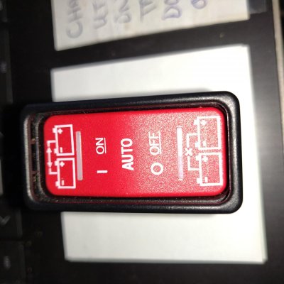
The S-P contactor is rated for 12v starter current. That system has been on the boat for 19yrs. and works well.

Indeed if the Starter Battery #1 4-way switch was in position 1, 2, or Off, the starter batteries would not get charged. I would most always leave it on Both, the other two positions are for an emergency start scenario. In Both position, the battery banks would automatically isolate when the engine was shut down.

I've read enough stories about large battery bank dead short fires to really like the idea of fuses on the positive output of each bank.


Will, I have a couple of questions about the design: The series/Parallel contactor is it designed to handle the 12 volt starter current? All of them I've seen are designed to handle the current at 24 volts and the contacts are sized for that current load. another question is it seems possible to have the switch in a position that the starter bank would not receive any charging current. I also would question why have fuses in a starter circuit. it seems to me any possible point of failure in the stater circuit could be problematic.
 
Last edited:
On my 220 amp Leece Neville alternator I attached a 4/0 cable from the alternator to the negative cable that connects the negative buss to the engine block. I'm still at a loss as to why they refer to alternator as having a ground. It's my experience that most all boats of this size have the DC negative buss and the engine block tied to the boat's bonding system, so I'm confused how this isolated ground is supposed to work. My 220 amp alternator directly charges my 900 amp house bank. If I were going to have only one alternator, it would do this and I would have a simple way of paralleling the house bank to the start battery when the engine is running or charge the start battery from the house bank.

Ted
 
I plan to use my 'isolated ground' (IG) alternator much like a 'regular' grounded-through-the-alternator-mount alternator. I.e., a 4/0 cable from the alternator Ground Terminal to the starter motor mounting bolt on the engine block. The House Bank negative 4/0 cable will go from the HB negative buss to the starter motor mounting bolt to complete the circuit. Unless some folks out there who know more about IG alternators say that's a no-no.

From my reading, a couple uses for IG alternators are in positive ground boats (precious few--probably old British:)), or boats with aluminum hulls.

It'd be great if someone more acquainted with IG alternators chimed in .
 
...It is basically just a house bank that runs typical house stuff (fridge, lights, etc.) and a start bank that runs the windlass, bow thruster, and main & generator starter motors...

I would personnally dedicate the start bank to what it is intended to... start.
Windlass or thruster are drawing a lot of amp and may leave you not able to start your engine what is not a pleasant surprise.

L
 
I prefer to have the choice of using either the start or house bank for those loads. I can raise the anchor and use the bow thruster on the house bank if I choose--or the start bank. Or start the engine first, which would have the high output alternator assisting either the house or start bank or both. Choice is good.
 
Dave, sorry, I somehow missed your message until just now. Lemme think on what you wrote, you might be right.

Regarding the ACR not closing until the alternator is putting out, one of the cool things about the Blue Sea ACR is that it comes with a remote-mounted (in wheelhouse) rocker switch (see photo) that allows several states of operation: remotely close the ACR, normal Auto (charge-sensing) operation, or remotely open the ACR. There is also a manual twist-the-yellow-lockout-knob on the ACR itself.

I originally had just an On/Off switch at Start Bat #1 as you said, maybe I can still do that. Will engage the old noodle on that....


Unlike Ted, I'm NOT good at interpreting schematics.

It looks to me as if the 1/2/Both switch will allow you to isolate the start bank for starting the engines. However, I don't think it will allow you to isolate the house bank to start the engines. The reason being that the ACR won't connect the house bank to the 1/2/Both switch unless there is a charging source to the battery (ie the voltage the relay reads is above its threshold).

So if for some reason you needed/wanted to start the engine with the house bank, you would need to switch the 1/2/Both switch to #1 (taking the start bank offline) but you would also have to switch the ACR closed manually.

In this way, I'm not sure I know what the addition of the 1/2/Both switch gives you? Why not just use an on/off switch in the start battery curcuit? With that in the On position, both banks will be combined when there is a charging source. If you want to start with the house bank and isolate the start bank, you manually close the ARC relay and turn the start bank Off. During normal operation, you would be starting with the start bank only.

I'm sure I am missing something....
 

Attachments

  • BlueSea ACR Remote Switch.jpg
    BlueSea ACR Remote Switch.jpg
    139.4 KB · Views: 45
Last edited:
You mentioned the remote switch in your initial post yet I failed to pay attention. Sorry. I was thinking about a switch on the ACR (which yours also has). The remote switch makes it convenient and easy as long as there is enough power to operate the relay.


Unless I'm missing something, it still seems as if your on/off switch on the start bank, along with your remote switch for your ACR would accomplish what you are after.
 
Indeed, I looked it over and you're right--thanks much. I was getting too enthusiastic/fancy (yes Ted). I changed the schematic to have the House Bank cross-feed and Start Bank Bat #1 positive cable both go directly to the Start Bank positive buss. Turning Start Bat #1 switch On or Off and using the ACR remote switch will do the same thing as the 4-way battery switch would do.
 
Anything that says "Auto" gives me concern. "Auto"matic things have been known to fail at the most inconvenient time.
Just my opinion.
 
Anything that says "Auto" gives me concern. "Auto"matic things have been known to fail at the most inconvenient time.
Just my opinion.


I get it, but I think the BlueSeas ACRs have been pretty bullet proof.
 
+1. It'll be more reliable than my memory over time would be....
 
You can also just manually control the latest Blue Seas ACR from the switch on the top if you don’t want another switch in the cockpit to accidentally leave in the wrong position.
 
You can also just manually control the latest Blue Seas ACR from the switch on the top if you don’t want another switch in the cockpit to accidentally leave in the wrong position.

I have the remote switch for my inverter. I mounted it in the saloon. I find it more convenient, placing close to the things I can put in the inverter, microwave and 2 galley outlets.
 
Could do that. Could also use a momentary push-button switch.
You can also just manually control the latest Blue Seas ACR from the switch on the top if you don’t want another switch in the cockpit to accidentally leave in the wrong position.
 
Got good answers on one, but thought I'd give the other original question of this thread another try since I haven't had any comments on it so far. Any knowledge about this most appreciated :flowers:!

For anyone out there familiar with Isolated Ground alternators: if my House & Start Bank negative busses are tied together at the engine block (e.g., starter housing mounting bolt--see Note 1 in wiring diagram attached to Post#1) with 4/0 cable, can I iinstall the negative side of my 200A alternator by just running a 4/0 cable from the alternator isolated ground to the same starter housing mounting bolt(s)? Any No-Nos (e.g., Ground loops) regarding doing this?
 
Last edited:
An isolated ground alternator uses a cable rather than the engine block for the ground line. It is better to use a copper cable than a big block of steel, with numerous gaskets, permatex, and other joints that can act as a poor conductor, compared to a heavy gauge copper line straight to the battery or regulator.

Think how many times the power has to jump from one part to the other to get to the engine ground strap. Even the bushings on the alternator mount, or the alternator tension arm, then through the front engine cover, and the engine block. If you start pumping 220 amps of power across a poor conductor (steel), you'll turn some of the current into heat, and also perhaps cook off the gasket glue. You can cause electrolytic corrosion.
 
Makes sense. Good summary--thank you.
 

Latest posts

Back
Top Bottom