Floor problem - Any idea?

The friendliest place on the web for anyone who enjoys boating.
If you have answers, please help by responding to the unanswered posts.
Didn't have a chance to go to the boat yet (around 0 F this weekend) but I found a few pictures of my setup. There is a lot of room under the engine. We can see one of the front mounts. Don't know if these are bigger than usual.


-- Edited by Fotoman on Sunday 12th of February 2012 06:47:44 PM


-- Edited by Fotoman on Sunday 12th of February 2012 06:51:59 PM
 

Attachments

  • _mg_4719.jpg
    _mg_4719.jpg
    89 KB · Views: 121
  • _mg_4726.jpg
    _mg_4726.jpg
    101.7 KB · Views: 125
  • p4093849.jpg
    p4093849.jpg
    162.5 KB · Views: 123
  • pb142658.jpg
    pb142658.jpg
    61.8 KB · Views: 117
I would be surprised if the engine was moved around much since any change in elevation would put it out of alignment with the shaft, unless there is a flexible coupler between the transmission and the shaft which after seing your photos there does not appear to be.

One possibility has been mentioned by Eric himself and that is if the boat was given a different transmission at some point and this required raising the engine so the transmission would mate up properly with the prop shaft. On most boats the shaft is a fixed entity and it enters the engine room at the angle established by the boat's construction. The engine/transmission mounting has to accommodate the shaft, not the other way round.


-- Edited by Marin on Sunday 12th of February 2012 06:49:24 PM
 
Marin wrote:
*

One possibility has been mentioned by Eric himself and that is if the boat was given a different transmission at some point and this required raising the engine so the transmission would mate up properly with the prop shaft. On most boats the shaft is a fixed entity and it enters the engine room at the angle established by the boat's construction. The engine/transmission mounting has to accommodate the shaft, not the other way round.
*A different transmission or even adding a longer reduction gear can cause the front of the engine to be a higher elevation. *It looked as if a reduction gear is on the rear of the transmission. *If a more compact reduction gear that will mate up can be found, it could be the easiest solution.
 
How about getting rid of the offending*item and go keel cooler.

Not hard to do. Just a thought.

SD
 
The header tank is part of the engine's coolant (antifreeze) system, not part of the raw water cooling system. It is not a heat exchanger, it is an expansion tank/reservoir for the coolant in the engine. If you keel-cooled the engine you'd still need the header tank.
 
Looking at the first pics in the most recent post, it looks like the engine mounts are located on those (new?) 6x6 (?) stringers, which are not glassed in and certainly do not appear to be "stock". Looks to me like the engine was pulled, stringers replaced or sistered in, with the result that the engine is sitting higher. This would've require some adjustment in the stern tube/prop shaft/cutless bearing alignment, but maybe once the engine was back in, they decided it was easier to realign aft than to pull the engine again. Just my guess. The right fix would probably be to re-mount the engine back a little lower, but $$$??? ... who knows what the owner's willing to live with.

Maybe with enough patience, you could gradually raise those house-leveling jacks (another creative solution I never saw) and put a little crown in the salon deck, enough to get the hatch to sit in there.
 
Is it just the camera angle or is the starboard mount adjusted higher than the port which is partially blocked from view.
 
ARoss wrote:


Maybe with enough patience, you could gradually raise those house-leveling jacks (another creative solution I never saw) and put a little crown in the salon deck, enough to get the hatch to sit in there.
*How about just raising the water line?
biggrin.gif


*

Really about the shortest transmission I have see is a Hurth. *Even with a reduction gear they are shorter than average. *If it would mate up, it could work to lover the engine.


-- Edited by Moonstruck on Sunday 12th of February 2012 09:53:20 PM
 
Why not just move the expansion tank? Location is not critical. I have two generators and mounted the expansion tanks outside the sound enclosures to they would be more accessible.
 
The header tank on an FL120 is not the same as the expansion or recovery tank on a car (or the ones you are referring to on your engines and generator). There is a kit available from American Diesel that consists of an automotive-type recovery bottle and a new header tank neck and cap that turns the coolant system on an FL120 into an self-returning system like a car's. The plastic recovery tank in the kit can be remote mounted. The header tank on the front of the engine does not perform the same function and it cannot be remote mounted, or at least not with some significant custom machining and careful mounting if it can be done at all.

As I said earlier, the level of coolant in the header tank has a critical relationship to the level of coolant in the Lehman cooled exhaust manifold. The header tank on an FL120 is hard bolted to a mating face on the top of the thermostat housing. In this respect it is a built-in component of the engine's cooling system, not a simple plastic overflow tank that accepts excess coolant as it heats up and then has that excess pulled back into the engine as it cools down like the one on a car.

I have never heard of an instance where the header tank of an FL120 was removed, a coolant elbow machined to fit onto the machined face of the thermostat housing and connect to the remote-mounted tank, and the tank remounted with the proper hose connections and at the exact right height to maintain the proper level of coolant in the exhaust manifold.

The plastic expansion tank sold by AD is intended to be remote mounted, same as it is in a car. It is plumbed to the new overflow pipe that is part of the replacement neck for the engine's header tank. The pressure and expanded volume of coolant in the engine's coolant passages is forced out of the header tank--- same as it's forced out of the upper end of a car's radiator--- into the remote-mounted recovery tank. As the engine and coolant cools after the engine is shut off, the vacuum from the reducing coolant volume pulls the coolant from the recovery tank back into the header tank on the engine to maintain the correct coolant level in the same way the coolant is pulled back into the radiator of a vehicle.

While some people call the header tank on the FL120 an "expansion tank," it really isn't. It is the engine's coolant reservoir and as such retains the correct level of coolant necessary to ensure proper cooling of the exhaust manifold (as well as the rest of the engine).

If an FL120 is not fitted with an after-market coolant recovery kit, the expanding volume of coolant in the hot engine is simply blown out the overflow tube of the header tank into the bilge or engine pan. It is not recovered. Over time, if the coolant level in the header tanks is not renewed, the coolant level in the tank will drop to the point where an air pocket can form in the upper front end of the exhaust manifold. If the level in the header tank is low enough, the air pocket in the exhaust manifold will become trapped there and a severe hot spot will develop. This can eventually burn through the inside of the manifold and ruin it.

After learning all this from Bob Smith at American Diesel, I purchased a pair of their recovery tank kits. However, I have never gotten around to installing them. Instead, I use a "poor man's" recovery tank on each engine. I put a long hose on the overflow tube of each engine's header tank and led it down into an empty plastic bottle in the engine drip pan. I then periodically pour the coolant that gets blown out of the header tank into the bottle back into the tank.

Unfortunately, simply hooking a recovery tank to the stock header tank's overflow pipe will not result in the system drawing the coolant back into the tank because the stock tank cap doesn't allow this. This is why American Diesel's recovery bottle kit includes a new neck for the header tank and a different type of cap, both of which allow coolant to be pulled fairly quickly back into the engine as it cools, same as a car.

One of my pre-start checks on our boat when the engines are cold is to crack open the petcock on the top front of the exhaust manifold of each engine to ensure that coolant come out out. *This ensures that there is no air pocket in the manifold cooling passage. *I do this with the cap off the header tank. *Otherwise the seal of the cap on the tank will not allow the coolant to come up through the petcock and eliminate any air pocket that might be there.

And NEVER open that petcock when the engine is running or hot (that's out of the operator's manual).


-- Edited by Marin on Monday 13th of February 2012 01:49:58 AM
 
ARoss wrote:
Looking at the first pics in the most recent post, it looks like the engine mounts are located on those (new?) 6x6 (?) stringers, which are not glassed in and certainly do not appear to be "stock". Looks to me like the engine was pulled, stringers replaced or sistered in, with the result that the engine is sitting higher. This would've require some adjustment in the stern tube/prop shaft/cutless bearing alignment, but maybe once the engine was back in, they decided it was easier to realign aft than to pull the engine again. Just my guess. The right fix would probably be to re-mount the engine back a little lower, but $$$??? ... who knows what the owner's willing to live with.

Maybe with enough patience, you could gradually raise those house-leveling jacks (another creative solution I never saw) and put a little crown in the salon deck, enough to get the hatch to sit in there.


*
*

This is my guess too from the new pic...the engine stringers were shot and someone did a REALLY amatuerish job fixing them and wound up raising the engine...how ???? I have no idea because it would change the angle through the shaft log and changing that plus the cutlass bearings would have been a BIG deal compared to fixing stringers correctly. UNLESS the cutlass is wearing REALLY funny which means the whole alignment issue needs to be addressed and the cabin sole is small potatoes.


-- Edited by psneeld on Monday 13th of February 2012 07:08:36 AM


-- Edited by psneeld on Monday 13th of February 2012 07:09:11 AM
 
psneeld wrote:ARoss wrote:
Looking at the first pics in the most recent post, it looks like the engine mounts are located on those (new?) 6x6 (?) stringers, which are not glassed in and certainly do not appear to be "stock". Looks to me like the engine was pulled, stringers replaced or sistered in, with the result that the engine is sitting higher. This would've require some adjustment in the stern tube/prop shaft/cutless bearing alignment, but maybe once the engine was back in, they decided it was easier to realign aft than to pull the engine again. Just my guess. The right fix would probably be to re-mount the engine back a little lower, but $$$??? ... who knows what the owner's willing to live with.

Maybe with enough patience, you could gradually raise those house-leveling jacks (another creative solution I never saw) and put a little crown in the salon deck, enough to get the hatch to sit in there.


*
*

This is my guess too from the new pic...the engine stringers were shot and someone did a REALLY amatuerish job fixing them and wound up raising the engine...how ???? I have no idea because it would change the angle through the shaft log and changing that plus the cutlass bearings would have been a BIG deal compared to fixing stringers correctly. UNLESS the cutlass is wearing REALLY funny which means the whole alignment issue needs to be addressed and the cabin sole is small potatoes.


-- Edited by psneeld on Monday 13th of February 2012 07:08:36 AM


-- Edited by psneeld on Monday 13th of February 2012 07:09:11 AM

*I'm betting that that engine can be lowered right were it sits.* It looks like it has an inch or inch and a half worth of room on the starboard side ans you can't see the port side but it is probably the same.* So lower it check the alignment and see where you are at.

I still don't know how any of this got by a survey.

As Marin says the tank is not an expansion tank like the new engines have.* Keep in mind this engine was used before cars and*trucks had Them either.* But modifiying the engine is not the correct fix.* Plain and simple.
 
This is my guess too from the new pic...the engine stringers were shot and someone did a REALLY amatuerish job fixing them and wound up raising the engine...how ???? I have no idea because it would change the angle through the shaft log and changing that plus the cutlass bearings would have been a BIG deal compared to fixing stringers correctly. UNLESS the cutlass is wearing REALLY funny which means the whole alignment issue needs to be addressed and the cabin sole is small potatoes.
*I'm betting that that engine can be lowered right were it sits.* It looks like it has an inch or inch and a half worth of room on the starboard side ans you can't see the port side but it is probably the same.* So lower it check the alignment and see where you are at.

I still don't know how any of this got by a survey.

This is an interesting developement (well, kind of!). I'm going to the boat tomorrow so I'll look at this with a different set of eyes for sure.

So if I lower the engine as it sits right now, would a flexible coupling give me a bit of help if the alignment is not 100% true? Also, will I have to move the engine forward to insert the coupling or will the shaft just pull back a bit?
 
Fotoman wrote:
This is my guess too from the new pic...the engine stringers were shot and someone did a REALLY amatuerish job fixing them and wound up raising the engine...how ???? I have no idea because it would change the angle through the shaft log and changing that plus the cutlass bearings would have been a BIG deal compared to fixing stringers correctly. UNLESS the cutlass is wearing REALLY funny which means the whole alignment issue needs to be addressed and the cabin sole is small potatoes.
*I'm betting that that engine can be lowered right were it sits.* It looks like it has an inch or inch and a half worth of room on the starboard side ans you can't see the port side but it is probably the same.* So lower it check the alignment and see where you are at.

I still don't know how any of this got by a survey.

This is an interesting developement (well, kind of!). I'm going to the boat tomorrow so I'll look at this with a different set of eyes for sure.

So if I lower the engine as it sits right now, would a flexible coupling give me a bit of help if the alignment is not 100% true? Also, will I have to move the engine forward to insert the coupling or will the shaft just pull back a bit?

*I would first take the coupling apart as it is and it might not be correct as it is.* Then I would lower the engine as much as needed both front and rear as needed to clear the hatch by at least one inch.* Mate the shaft up and see what you have.* You might not have a problem at all.* Everyone likes to jump to conclusions.* Wait and see what you have.

As far as the flex coupling goes you don't move the engine.* First you have to see if when you install it if the prop clears the rudder.* If it does you are good to go, if not the shaft needs to be shortened. But keep in mind that the flex is not really to correct an alignment problem it is a transmission saver as in a shear point instead of gears breaking.* I don't think it is the correct repair for your problem.
 
Thanks JD. It makes sense. I'll take the coupling apart and see what happens with the shaft.

And thanks Marin. Your answers are always very detailed and informative.

I briefly thought about moving the header tank or cutting it to make it smaller but I figured it would be just a patch anyway (if it was possible at all wich looks like it's not). I did talk to Brian at AD about my problem last Friday because my initial thought was that the header tank might have been changed for a bigger one. But it's not the case, I have the original part. He did talk about the replacement part with the expansion tank but he said it was not smaller and wouldn't solve my problem. If there was a way to move the header tank, Im sure he would have mentionned it at some point during our discussion.

I'd rather go the extra mile(s) and figure out the cause of the problem. As some have mentionned, the boat did not get out of the factory that way. Something happened to screw things up along the way. Half the job is investigating to figure out what it was.*The other half is figuring out a*solution. And*the last half is getting the job done. *Wich means a boat job is actually worth 150%. I'm sure you all know what I mean.

*


-- Edited by Fotoman on Monday 13th of February 2012 11:13:48 AM
 
Marin wrote:
The header tank on an FL120 is not the same as the expansion or recovery tank on a car (or the ones you are referring to on your engines and generator). There is a kit available from American Diesel that consists of an automotive-type recovery bottle and a new header tank neck and cap that turns the coolant system on an FL120 into an self-returning system like a car's. The plastic recovery tank in the kit can be remote mounted.
* * * ** My boat is set up exactly as outlined above.

It was next to impossible to check the coolant level and fill the oil as both were within 2 inches of the salon floor.

The fix? I cut a square hole out of the salon floor, saving the plug to be used as a hatch later. The hole is directly over the oil fill & expansion tank cap. The old cap was directly underneath a longitudinal stringer and had to be relocated 4 inches to the left so as to facilitate an easier removal of the cap. Changes to the expansion tank were accomplished at a radiator shop where the old filler neck was removed, the hole sealed and relocated 4 inches to the left.

A recovery bottle was located directly under the settee cushion and a hose installed that ran from the bottom of the plastic tank to the filler neck on the expansion tank. Now all I have to do to check my coolant level is pick up the settee cushion and check the level of coolant by sight. (Should be 2 inches of coolant showing when the engine is cold.)

The plug (cut out) was trimmed, a pull ring installed* & placed back over the hole.

Is this anal? I don't think so as now when it's time to check all the fluids, it can be accomlished without leaving the salon. (The transmission fluid being the only exception as its filler is directly below the "day hatch" by the salon table)

Why these things are not done by the factory can only be explained by:" the folks that build these boats, for the most part, are not cruisers!"
 

Attachments

  • coolant cap after.jpg
    coolant cap after.jpg
    63.2 KB · Views: 89
  • settee.jpg
    settee.jpg
    126 KB · Views: 97
  • close hatch.jpg
    close hatch.jpg
    44.9 KB · Views: 90
A truly flexible shaft coupler, like an Aqua Drive, requires some room to install it. From your earlier photo it appears you don't have much exposed shaft between the transmission and the stuffing box/shaft log. An Aqua Drive is intended to allow a softer engine mounting for less or no vibration in the boat. You cant simply put soft engine mounts on a hard-coupled engine because the engine will move around too much on the mounts and stress and wear the driveline and cutless bearings. But by putting what in essence is a U-joint in the driveline after the engine, you can now use soft mounts as the engine's movement will be compensated for by the U-joint coupler. Here is the URL for Aqua Drive if you want to find out more about them http://www.aquadrive.net/ There may be other makes or types of flexible couplings--- Aqua Drive is the only one I know about.

I'm not familiar enough with hull construction to know how easy or hard it is to change the angle of a prop shaft as it comes through the hull. It sounds to me like it's a major job but I simply don't know. But if this is not done, or can't be done, and if the alignment of your engine and drive shaft are correct now, then changing the height or angle of you engine will mis-align it with the propshaft and you'll have a new problem to deal with.

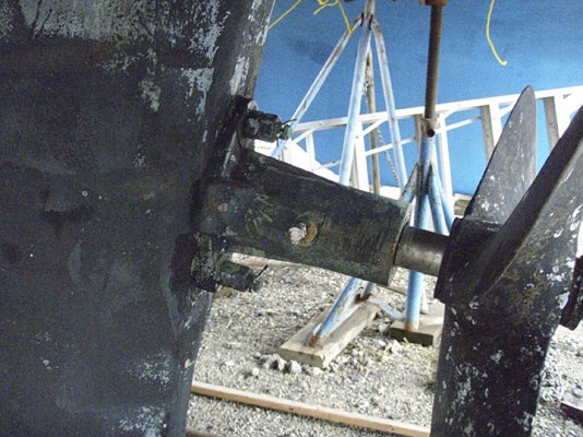
Propshafts are flexible. The amount of flexibility will be dependent on the length of the shaft and length of its unsupported segments. This is generally the greatest in a twin-engine boat like ours. What this means is that a certain amount of mis-alignment between the engine/transmission and the shaft can occur and be compensated for by the shaft's flexing. The symptom is often a vibration and over time it's hard on everything--- cutless bearings, motor mounts, and the shaft itself.

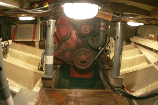
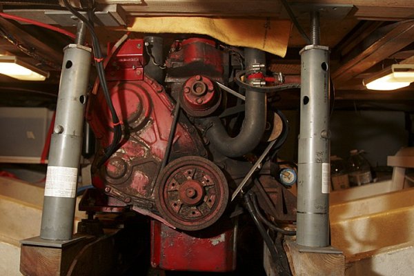
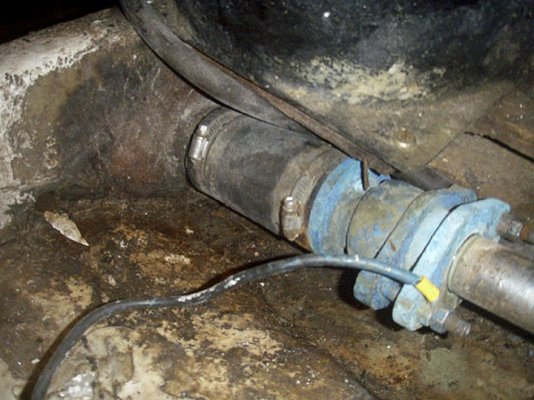
In a single like yours there seems to be very little shaft length between the shaft log and the shaft coupler on the transmission's output shaft. And I'm guessing there's not much exposed shaft between the rear bearing and the prop itself. So I would think there is little to no opportunity for the shaft in your boat to flex. Do you get a lot of vibration when you run the boat? Tough question to judge because vibration can be generated by a lot of things.

A good first step is to do what others have suggested and first check the alignment of the engine to the shaft. This is relatively easily done by separating the shaft coupler and sliding the shaft back a fraction of an inche and measuring with a feeler gauge all the way aorund the gap between the two coupler halves. If the gap is the same all the way around then the engine and shaft are in the correct alignment. There is a certain amount of tolerance in this measurement-- our diesel shop has told us what it is but I don't remember so if you decide to do this yourself check with a shop to get the correct tolerance number.

If you find the alignment is correct, then it would seem you have three choices. One, leave the engine where it is, lower it, and realign the shaft itself to the engine by changing the angle the shaft comes through the hull. Major big job I would think but I don't know.. Two, the coupler can be removed, the shaft shortened a little bit (you don't have much to work with here judging from your photo) and the engine slid back and lowered a wee bit in the same alignment to mate up with the shorter shaft.* However, I'm not sure this would actually get you the clearance you need so work out the geometry very carefully before you decide to try this. Three, relieve the underside of the hatch in the manner some earlier posters have suggested.
 
SeaHorse II wrote:The fix? I cut a square hole out of the salon floor, saving the plug to be used as a hatch later.
This is exactly the same solution suggested by a shipwright when we were trying to figure out a way to access the coolant fill cap on our Onan Jurassic Series MDJE generator, which had been repositioned in the engine room when the new fuel tanks had been installed by the previous owner.

Adding coolant required removing the entire multi-section sound shield and using a funnel and a long tube to reach the fill cap which had only a few inches of clearance above it.* The sound shield has a factory hole in the top over the cap--- the challenge was getting to it.

The shipwright suggested doing exaclty what Walt did--- carefully cut out a section of the parquet floor and sub-floor, make a nice teak frame around the hold with a lip under it to hold the new "hatch" and then put a nice teak edge around the little hatch itself with a finger pull inset into the parquet.* The whole thing is about 1' by 6" and it looks like the factory put it in.* (The shipwright did the work, not me, which is why it looks so good.)
 
Marin, there is no vibration when I'm underway apart from the normal shaking of the engine but even that is minimal. And you're right, there is not much shaft showing outside. On the other hand, there is plenty of clearance between the prop and the rudder. Maybe I could simply move the engine aft about 2 inches and then lower it to preserve the shaft alignment?

By the way, we can see a bolt on the side of the shaft housing in the picture. Always wondered what that bolt was for.

*
 

Attachments

  • pb142605.jpg
    pb142605.jpg
    156.6 KB · Views: 99
Logic and visualization indicates to me that moving the engine aft a mere two inches while maintaining the current alignment isn't going to buy you much of a reduction in engine height but I'm sure that could be accurately determined by drawing it all out to scale.
 
That bolt is probably to hold the cutlass bearing...most boats have set screws that don't show.

I have my prop off and shaft out as I had a new split coupling put on my shaft and some other work.

I can shine a light up the shaft log and see my tranny centered right in the hole...so I know that's good....as long as I can align the engine to the coupling...I'm set.* If your could get your shaft out...that would tell you in a second what's really going on as to how your engine sits.


-- Edited by psneeld on Monday 13th of February 2012 04:32:28 PM
 
Fotoman wrote:
Marin, there is no vibration when I'm underway apart from the normal shaking of the engine but even that is minimal. And you're right, there is not much shaft showing outside. On the other hand, there is plenty of clearance between the prop and the rudder. Maybe I could simply move the engine aft about 2 inches and then lower it to preserve the shaft alignment?

By the way, we can see a bolt on the side of the shaft housing in the picture. Always wondered what that bolt was for.

*
*Holds the cutlass bearing from turning or coming out.
 
Was there a zinc on that prop shaft when the boat was pulled?
 
Ok so I had a chance to go to the boat today. Here are a few pics. The port mounts shown in the pictures don't look like they can be lowered much. Also looked at the beams where they sit on the hull and no rot or sagging there. So I'm leaning towards the theory that the engine stringers might have been replaced at some point and they are higher than the stock ones. Or maybe it was a combination of things: changing the reduction box/transmission, changing the stringers. The engine ended up a few inches forward and a few inches higher.

It was too cold for me to undo the coupling and check the alignment. Maybe that will answer a few questions.

Question: are those mounts standard size?

Not sure why someone stacked 4-5 nuts on these bolts either.


-- Edited by Fotoman on Tuesday 14th of February 2012 03:16:20 PM
 

Attachments

  • p2144347.jpg
    p2144347.jpg
    162.7 KB · Views: 81
  • p2144350.jpg
    p2144350.jpg
    123.1 KB · Views: 104
  • p2144349.jpg
    p2144349.jpg
    140.8 KB · Views: 90
  • p2144348.jpg
    p2144348.jpg
    156.9 KB · Views: 88
Fotoman wrote:

Question: are those mounts standard size?
I can't tell the size from the photos but they are very similar in style to the ones we have on our boat.

Two things to be careful of with these mounts if they are similar to ours:

1. Make sure they haven't "collapsed."** Over time, the rubber doughnut in the mount will compress until it is no longer holding the upper and lower parts of the mount apart and you get metal-to-metal contact.* When that happens, the mount needs to be replaced as it is no longer providing any vibration or shock isolation at all.* Looking at your second photo, I wonder if this has not happened on that mount, but without knowing exactly how the mount is constructed it's impossible to tell for sure.

2.* The rubber in the mount will deteriorate if it gets oily and stays oily.* Judging from your first photo, that mount at least seems quite oil-covered.* My advice would be to give them a thorough cleaning.* Unless, of course, the rubber has compressed or deteriorated enough to allow metal to metal contact in which case keeping the mount oil-free doesn't matter anymore.


-- Edited by Marin on Tuesday 14th of February 2012 03:47:56 PM
 
Could this boat have come with a 4 and been retrofitted with a six. This would make the engine higher in the front as the six is two cylinders longer.
 
Mr. Fotoman,
I tend to agree with Mr. Marin. That mount in pic. #2 appears shot. MY question is: Why is there such a difference in stud lenghts holding the mounts down? Extra nuts are probably on there maybe because PO didn't have a deep socket or possibly the stud threads were damaged.
If you do replace the mounts, trim down those long studs and run a die over the threads. If the threads are damaged beyond use, you'll have to replace them anyway.
You appear to have a self aligning stuffing box so alignment may be WAY off.
 
Mr. Fotoman,
The housing holding your packing material aginst the propshaft is NOT attached hard to your hull. There is that piece of rubber tubing (6"-8" long) between the hull and the housing. This allows the housing to "float" and self align itself. At least this is how it was explained to me.
 

Latest posts

Back
Top Bottom