Winter Project I: Charging System Upgrade

The friendliest place on the web for anyone who enjoys boating.
If you have answers, please help by responding to the unanswered posts.

Tom.B

Moderator Emeritus
Joined
Jul 30, 2009
Messages
5,839
Location
USA
Vessel Name
Skinny Dippin'
Vessel Make
Navigator 4200 Classic
It's time for Skinny Dippin's annual winter project. This year I have decided to upgrade the charging system. Although, there is a plumbing upgrade to do in order to make room for this and I'll open a thread for that in the General Maintenance forum.

Over the past 2.5 years we've owned her, I have never completely understood the charging system, thus, never really trusted it. As with the great fuel system upgrade I undertook last year, I intend to learn everything I can about this system so that next season, we'll be able to spend much more time at anchor with the comfort of knowing that we'll have enough power to enjoy the time and still start The Great Dr. Perky (yes, our engine has a name) in the morning.

The basic plan is similar to what we did with the fuel system which is to centralize the major components on a piece of King Starboard to allow for ease of maintenance and control. I'm adding a new "smarter" charger (but it's not too smart), a new 2000W inverter (never had one on this boat), 4 new 6V golf cart batteries (Trojans maybe), a new starter battery, and all new switches and wire.

I must once again thank RickB for all his help with this so far. Although, we have disagree on a few of the particulars, Rick has once again simplified a rig I had setup to be WAY too complex.

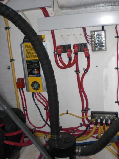
Below is a picture the first mock-up of the parts I have so far. The two switches on the left are for starter disconnect and battery combining. The single switch in the center is house battery cutoff. Just above is the t-type 400A main fuse (although I may not use it once I figure out my combined loads). On the right is an Iota 55A charger with IQ4. Upper left is a Balmar Duo Charge to trickle the start battery while the alternator charges the house bank.

**NOTE** There will be a ground buss on the lower right... It was on backorder. :-(


elecmockup1 by GonzoF1, on Flickr


-- Edited by GonzoF1 on Monday 16th of January 2012 09:53:43 AM
 
Here are a few pics of the current state of things:

This is the house bank. That switch and breaker are for the genset and will be moved to the board.


P1000954a by GonzoF1, on Flickr

Just to the right (less than a foot away) is the wall space I intend to mount it all. I'm going to move the Fireboy to where the old Newmar charger currently sits.


P1000960a by GonzoF1, on Flickr

Just so you can see. This is some of the stuff I want to do away with.


P1000797 by GonzoF1, on Flickr


-- Edited by GonzoF1 on Monday 16th of January 2012 10:08:30 AM
 
Looks like a great setup, Note that the IOTA can be 'adjusted' for open voltage if necessary. I am told this will affect the charging profile in a linear manner.

There is an access point on the back of the unit for a screwdriver to make an adjustment in a potentiometer.

Depending on the batteries you choose for the house bank, they may require slightly different charging voltages.


On the fuse holders on the positive buss, why not fuse at the battery bank instead?


Good luck
 
I will be fusing the entire bank, but also need to protect long wires to the alternator, windlass, and inverter (it will be mounted in the galley a few feet away).


-- Edited by GonzoF1 on Monday 16th of January 2012 10:31:20 AM
 
GonzoF1 wrote:
I will be fusing the entire bank, but also need to protect long wires to the alternator, windlass, and inverter (it will be mounted in the galley a few feet away).


-- Edited by GonzoF1 on Monday 16th of January 2012 10:31:20 AM
*Tom, I don't know what you mean by a few feet, but inverters can be sensitie to voltage drops. *Usually about 4-5 ft is the most you would want an inverter away from the batteries. *It can be tricky as some inverters are sensitive to heat also.
 
Thanks Don. Actually, I suspect the cable will only be 3-4 feet. I am heeding that advice about higher temp areas and mounting it just thru the wall of the engine bay in a little-used space below the refrigerator. The wire literally has about 3' of linear travel then goes thru the bulkhead and it in the locker where it mounts. At that point, the only extra length will be about a foot to allow for pulling it out to service it.
 
GonzoF1 wrote:
Thanks Don. Actually, I suspect the cable will only be 3-4 feet. I am heeding that advice about higher temp areas and mounting it just thru the wall of the engine bay in a little-used space below the refrigerator. The wire literally has about 3' of linear travel then goes thru the bulkhead and it in the locker where it mounts. At that point, the only extra length will be about a foot to allow for pulling it out to service it.
*Sounds like a good place. *You will need a good air change going on as the inverter with create its own heat. *It's probably a good idea to download a manual for the model you plan to install to make certain that all the requirements are met.
 
I have a question for the experts... Should I keep the welding wire or pull it out and use new?
 
GonzoF1 wrote:
I have a question for the experts... Should I keep the welding wire or pull it out and use new?
No Expert.

But think you should strongly consider new, tinned and*properly colored non-welding*cable.* More bucks for sure, but more safety and longer service life.

How long are you planning on keeping*the boat?*
smile.gif
 
FWIW, I'm no expert either, but I have used welding cable for years.* I pulled the wiring out of my old boat after 20 years and it was as good as new.* Welding wire is far more flexible and easy to route.* Think of the envirnment that the weld wire is made to survive, places and things it is drug over, hot sparks being showered on it.* It is good stuff.* That said, it is not tinned.* So what? I think it's not too hard to work around that short coming.* I first flux the inside of the lug as well as the wire, then crimp, then solder.* I flux and flow solder over the outside of the lug.* Then seal the whole thing with adhesive lined heat shrink.* Red for positive, black for ground.* How is this to corrode?* Nothing can come between the wire and the lug, since it is solid with solder.* The adhesive lined heat shrink seals the whole thing too.* It is in a dry place, not underwater.* The bolted connections get a good coat of Vasoline or dielectric grease too.* Very effective and cheap to boot.* The Positive wire isn't red, so what?* I'm not going to cut into the middle of a wire.* The ends where the connections are made are color coded.
 
Not saying that welding cable is bad, just not as good.*

Used it for 25 years on my former boat, and the only issues were a short piece of softened cover where the cable was exposed to oil residue, and a couple of terminals that needed to be redone probably because I hadn't tinned the wire sufficiently prior to solder.

*
 
What do you want the new setup to DO?

If anchoring out is your desire the first spending should be on an SOC meter , so you know whats happening.

"Knowledge is Power " (FB)
 
I ordered a Victron 602 yesterday, Fred. Thanks :-D

Next question. Connect windlass to house bank or starter battery? Since I plan to move the alternator output to the house bank and use a Duo Charger (Echo Charger) for the starter battery. I think that since the windlass is used primarily when the engine is running, the house bank might be the smart move. However, I hate to chip away at a fully charged house bank just when I need it to be at 100%.
 
Nicest is a special , usually AGM start style battery very near the windlass or bow thruster.

Charged from the engine it will provide BIG power for a short time , and you can get by with smaller cabeling (price 40 ft of 04).

The batt will not out gas and is your "Ace in the hole" should you kill everything else.

It should start the noisemaker , to charge the engine batts , if required.
 
Thanks Fred... I considered a 3rd battery, but not worth the money at this point.

Speaking of money... The UPS man brought some more parts! Backordered bussbar, Victron monitor, bronze fittings, WAY heavy duty AWAB band clamps ("This one time, at band clamp..." :-D ), but the frosting on this cake is my new giant FTZ crimping tool!!!! Very phallic and I will cherish it forever.


stuff by GonzoF1, on Flickr


penis by GonzoF1, on Flickr
 
I took a drive to the boat on Friday to try the size of the mounting board. What I learned was that the original layout in the first post will put the switches way out of reach behind the batteries. There are also a few other limitations I have found. Soooooooo, I've had to rethink the layout and have come up with a few options.

The first two pics are using the longer but more narrow board. The third is a shorter fatter attempt. Unfortunately, I may have to have a "hybrid" shaped piece. Asymmetrical ain't my style, but I may not have a choice here.

**NOTE** I suppose that I still haven't put it completely out of the design possibilities that the switches could make it to inside the salon. I read the thread about it and considered the adjustment. However, it adds to the cost (longer wire runs) and takes away some of the beauty and continuity of having all the electrics in one nice neat little package.


elecmockup2 by GonzoF1, on Flickr


elecmockup4 by GonzoF1, on Flickr


elecmockup3 by GonzoF1, on Flickr
 
A couple of my thoughts.

I know some folks use welding wire "with no problems", but IMO it has no place on a boat. First, it does not meet ABYC standards. Second, the fine*strands that make it limber also make it wick moisture. Aslo don't like soldering connections, it makes them brittle. Third, I've pulled welding wire out of bilges of boat where the insulation was completely deteriorated. Literally falling off the wire. I personally wouldn't use anything but tinned marine cable.

I suggest you go the extra mile and move your switches outside the engine room. ABYC, again, suggests they always be outside the engine space. I have rewired my boat where all the battery switches are in the salon and am very happy with it. For the main engine start switch I used one of the Blue Sea Systems remote controlled switches (part # 7700). It is a latching type of relay so it doesn't consume any power except to latch or unlatch. Also has a manual lock out on the switch itself for working on the engine, etc.

Since you obviously want to do this right, you may also want to study ABYC reccomendations about over current protection. (fuses) For unprotected wire they must be within 7" of power source (battery, power terminal). If you use chafe protection (think split loom) you can extend that to 40". The fuse is to protect the wire in case of a break in insulation, so it make sense to get it as close to the battery as possible.

By the way, a starting circuit (main engine or genset) is the only circuit allowed to not have a fuse.

I commend you on your aproach to this project. Nothing like a neat, well thought out electrical system that is easy for anyone looking at it, operating it, or troubleshooting it to understand.

Here is a poor quality pic of some of my battery switches. The house switch is at the house panel, and the inverter switch is near it. Fuses for all are very close to the batteries and labeled. I had ran out of room on my ac panel so the breaker you see is for my second battery charger. I've since expanded the ac panel also.

*

*

*


-- Edited by Brent Hodges on Sunday 22nd of January 2012 04:51:44 PM
 

Attachments

  • batt switches.jpg
    batt switches.jpg
    109.2 KB · Views: 149
Jay N wrote:
Not saying that welding cable is bad, just not as good...*
Either will work, but if you're going through all this effort why not use tinned marine cable.* Change from black to yellow for the grounds which is the new standard for marine DC systems.* It reduces the chance of incorrectly connecting the AC hot with the DC ground.
 
Larry M wrote:Jay N wrote:
Not saying that welding cable is bad, just not as good...*
Either will work, but if you're going through all this effort why not use tinned marine cable.* Change from black to yellow for the grounds which is the new standard for marine DC systems.* It reduces the chance of incorrectly connecting the AC hot with the DC ground.

*Larry, thanks for that information. *The DC grounds on my boat are yelow. *I just didn't know why. *We have also used yellow for additional equipment added.
 

Attachments

  • moonstruck sabre 42 battery wiring 003.jpg
    moonstruck sabre 42 battery wiring 003.jpg
    91 KB · Views: 155
After giving it some thought, I am now thinking that I am going to recess the three big switches into the lowest step of my port side stairs that lead out the side door. I'll lose a little storage in the step, but I think if I recess them, they will not get torn up (going to fab a plexiglass door over them too). Seeing that the steps are just inches above the house batteries and only a foot away from where I was going to mount all of this hardware, the increase in cost for cable will be negligible. It will also provide a little more room on my board to neatly route cables around.

Besides... now I get to buy a big-azz hole saw. :-D
 
You won't be sorry. It will be a much neater, and more correct install.

And more tools are always a good thing! My lady friend has decided that my work van is not really that as much as it is a giant toy box!* :eek:)
 
At the boat this weekend and got to the install the inverter.

Here is the space just under the stairs into the galley (we are galley-down) in a currently unused cabinet below the "pantry" locker. That door on the right is engine room access (I have NO clue why it's there) and the house batteries are literally about 18" to the right of that. So the run of the inverter wires will about 5-6' (max) each way.

invert1 by GonzoF1, on Flickr

Sorry I didn't take any pics of the actual install, but here is the finished placement.

invert2 by GonzoF1, on Flickr

Here is the idea. I found some keyboard tray runners in the house and adapted them to this project. Add a teak and away we go.

invert3 by GonzoF1, on Flickr

This allows it to slide out for easier service access!

invert4 by GonzoF1, on Flickr

Here is the final look. The door is missing here so that I can bring it home to install a vent (maybe with a battery-powered fan) for better air circulation. However, as low as that space is in the boat, it stays pretty cool in there. I'll eventually wire it to the breaker panel and remote mount the control panel, but for now, once it's hooked up, we'll just use a power strip with a long cord.

invert_5 by GonzoF1, on Flickr

-- Edited by GonzoF1 on Sunday 5th of February 2012 03:33:14 PM
 
The install looks really good, particularly the slide out for eventual servicing.* However you've used some terminology that I'm not familiar with - what is "unused cabinet below the 'pantry' locker"?* I'm not familar with*unused space in the boating context.

*
 
I found a teak colored A/C vent at Home Depot and put it on the door. Looks good enough to me.


ventpanel by GonzoF1, on Flickr
 
Nice Job! I love the pull out idea.
 
Gonzo

I have the same engine room access door under my galley steps. I have owned the boat 18 yrs. That door was opened once in the first year, just to figure out why it was there, but I failed, and like you, don't know why.
You do nice work!

Bob:
I think he meant to say "inaccessible". That makes more sense in the boating context.
 
I'm wondering if I should just latch it a bit more securely and mount the Fireboy extinguisher to the engine room side of it. I suppose that if I was going to service the holding tank, the door *could* come in handy.

As I sit here, I wonder if it would make getting batteries in and out of the engine room easier. You wouldn't be handing them down into the hatch from above to someone trying to maneuver themselves AND the batteries to the floor in that small space (see pics above), but could set them on the salon floor with the main hatch closed, then stand in the galley and move them to the galley floor, then open the door to set them on the engine room floor, then finally jump into the engine room only to have to lift them into place. Did that make sense?

That's interesting only because when I read your post, I was just sitting here doodling the design of a removable battery loading tray to possible use to ease in the new battery loading process.

Tom-
 
Ya know those tools.

I used to buy them and found out I have a lot of tools I used once.

Now I rent them $10.00 bucks for the weekend return it and good to go.

If I need*It can I borrow yours?
smile.gif


All kidding aside you got the TSU (Trick Set Up)

Sort of looks like mine.

SD


-- Edited by skipperdude on Monday 20th of February 2012 10:46:11 AM
 
Anyone know what gauge the starter wire should be? I've looked up all my other DC loads on the boat, but I am not completely sure what gauge the starter wire should be because I don't know what the starter creates as a load. Standard AC Delco starter and the round trip distance to the starter from the battery could be 20'-25' depending on if I decide to move the battery location. Google might know too. I'll ask them next :)

(I was thinking 1/0 for this.)
 
There is no downside , besides co$t to 4/0.

A case where "bigger actually IS better".
 
Back
Top Bottom