Amp meter installation

The friendliest place on the web for anyone who enjoys boating.
If you have answers, please help by responding to the unanswered posts.

Phil23

Senior Member
Joined
Jul 29, 2013
Messages
207
Location
Russell NZ
Vessel Name
MV Unique
Vessel Make
Salthouse Coastal 35
OK so I have sorted my battery problems out all all are charging well and holding phew.
I would now like to install an amp meter to monitor amp usage at a glance in a 12 volt system what amperage gauge would I need and how should it be installed.
Only concerned with monitoring my house batteries which are 2 x 130amp hour batteries.
Advise appreciated.
 
Blue Seas has some amp meters with shunts. They make nice stuff.
 
If you are like me, a 30 amp boat, electric stove and microwave, get an analog Amp meter installed in the galley. Otherwise, you, like me, will be making many trips to the breaker panel when preparing a big meal. LOL
I like the analog meters so you can watch the trend and start turning things off as you approach the upper limits.
I have put the microwave on switchable power. I move the power to the microwave to the inverter as necessary
It is just a personal preference for analog meters and gauges but I am stuck with digital meters and gauges.
Other things need attending before that.
 
Hall-Effect Sensor for DC Ammeter -- no shunt

OK so I have sorted my battery problems out all all are charging well and holding phew.
I would now like to install an amp meter to monitor amp usage at a glance in a 12 volt system what amperage gauge would I need and how should it be installed.
Only concerned with monitoring my house batteries which are 2 x 130amp hour batteries.
Advise appreciated.

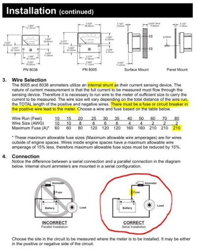
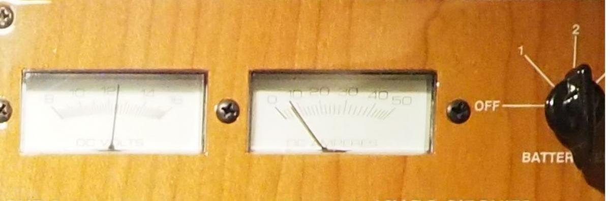
Back in the day, the only way to do this was with a shunt, which is a very low-ohm resistor, and an "ammeter" which is really a millivolt meter measuring the voltage drop across the "shunt" (resistor).

The problem with the shunt is that you are now cutting and terminating your main circuit feed to put the shunt inline. If the wiring is larger than 10AWG (and it typically is), these terminations require special crimping tools and connectors. If (for whatever reason) you overload your shunt it will burn up and turn into a "fuse". For this reason, you cannot install a shunt in areas that could contain flammable vapors.

The more modern solution is to measure the magnetic field around the wire, which increases in direct proportion to the current flowing. The problem is that Hall-Effect sensors that can do this used to be very expensive -- but no more.

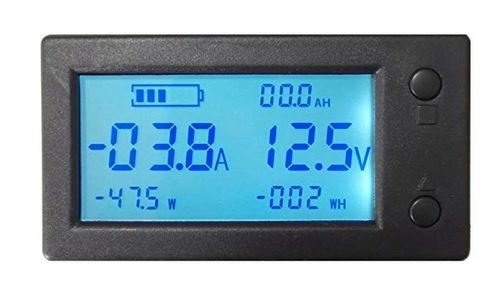
Here is a DIY version for $20, way less than the shunt based systems that cost >$200 and take half a day to install. Also, it's a digital voltmeter.

https://www.amazon.com/bayite-Digital-Current-Voltage-Transducer/dp/B01DDQM6Z4

Just feed the wire(s) through the ring, connect it to power and you're done.

Other nice features of this approach (aside from price):

- it shows you the amount and the direction of the current flow (charging vs discharging).

- You can feed multiple wires through the ring, with current flowing either way in each wire, and the meter will display the sum of the currents. For example, if your charger/alternator is putting out 60A and you are using 50A, this unit will tell you that your charge rate is 10A.

- Works equally well when used on the positive or negative wire.


Enjoy!
 
The above device is great for monitoring amp flow , but most folks simply want a gas gauge ,,how full are my house batts? ,,to know when to get underway , or crank up the noisemaker.


It would seem to be a great device for trouble shooting a DC setup.
 
Get a Victron SOC (State Of Charge) gauge. It will show you amps in, amps out, voltage, remaining percentage of battery bank capacity, and a number of other things. Works off a shunt in the negative battery cable.

Ted
 
As mentioned above, get a Victron BMV-712 battery monitor. That particular model can be monitored from your phone.
 
Ditto on the Victron state of charge gauge. It provides much more info than just how many amps you are using. It was one of the easier things that I have installed.
 
A voltmeter tells you what you need to know, like the one on your electrical panel, or plug a $2 digital meter in a (used to be called) cigarette plug. Same for 120 volts, if the voltage drops from your ambient charge (i.e. less than 118 volts in my marina or 120 on my genset) you are overloading.
 

Attachments

  • !12343.JPG
    !12343.JPG
    26.6 KB · Views: 86
OK I have a 30amp analogue amp meter with a built in shunt where do I take the positive wire and the negative wire to and should I include a fuse in either of the lines.
Thanks
Phil
 
That type of meter must be installed so ALL current to be measured goes through it. THat means depending upon where you want to mount the ammeter then you must feed all the house current through that meter with long, LARGE GUAGE wires to and from the batteries + to the meter then back to the boat wiring.

DO NOT DO IT. It is too small a capacity for the house batteries and it will not take long to blow it. It itself will become a fuse.

That is why the external shunt types are used so the major power wiring is disturbed as little as possible and not materially changed except for the shunt installation itself. Then from the shunt two light guage, likely #16 or # 14 AWG leads are run to the meter. These external shunt types only use , usually up to 50millivolts and 50 or so milliamps to make them work.

That meter is simply not suitable.
 
Hi C lectric what is your opinion on the above mentioned meter mentioned by Riverguy ex Amazon.
 
A SOC meter measures volts and amps going or coming from the batt set.

IT counts and remembers all the electron movement and will show a reading of what is currently remaining in the battery set.

A volt meter or amp meter shows an instant condition , has no memory.

If you need a "gas gauge" for the house batts the SOC meter is the simple way of knowing.

Here is one with a good reputation.

TriMetric Battery Monitor - - Bogart Engineering

www.bogartengineering.com/products/trimetrics.html
○Measures battery % full, based on amp hour measurements for accurate information on state of charge (SOC). This method is more accurate than monitors ...

[PDF]INSTRUCTIONS FOR - Bogart Engineering

www.bogartengineering.com/.../TM2030-Technical%20Manual%2006%202017REF....

IMPORTANT: The wiring installation for this meter, especially the shunt installation ... For warranty service, please email bogart@bogartengineering.com. ...... cause the “charge setpoints” to be achieved with a lower state of charge than ...
 
An ammeter alone won't tell you anything other than the current flowing through the shunt at any given point in time.

Unless you are keen on fiddling / programming, in order to keep a traditional Ah counter accurate for SOC, the Balmar Smartgauge (SOC only) or the new Balmar SG200 are both of the "self-learning" type. They can remain accurate without fiddling, re-programming or getting out-of-sync with the bank due to PSOC partial state of charge usage or batteries that age and lose capacity. The new SG200 also works with LiFePO4 for those interested..

If you think you're interested in a traditional Coulomb or Ah counter you may want to read the article below so you can keep it dialed in better.

Making Your Battery Monitor More Accurate

Also the correct installation of any shunt based battery monitor is pretty critical.

Installing A Shunt-Based Battery Monitor


.
 
OK I have a 30amp analogue amp meter with a built in shunt where do I take the positive wire and the negative wire to and should I include a fuse in either of the lines.
Thanks
Phil

See attached schematic from the Blue Sea 8005 internal shunt analog (25A) ammeter. Your 30 amp unit will be essentially identical.

On the presumption that the circuit you are measuring already has overcurrent protection at it's source (please verify), and that overcurrent protection is sized correctly for the wiring between the source and the load, then you do not need to add additional OCP just for the ammeter.

Put the ammeter AFTER the OCP device and before the load(s) you want to measure.

re: (from the O.P.) "I would now like to install an amp meter to monitor amp usage at a glance in a 12 volt..."

Your 0-30A analog ammeter will do exactly that...but with zero extra effort, you could use one of the hall-effect type digital devices, which don't require you to cut any wires. Given these are only about 20-30 bucks, and can tell you much more than a 0-30A analog meter, I'm not sure why you wouldnt choose that route instead.
 

Attachments

  • !2ammeter.JPG
    !2ammeter.JPG
    84.6 KB · Views: 104
Ok I can build boats, plumb boats and a 30 year veteran in marine coatings and associated resin systems however I am a complete "Bunny" when it comes to this electrical game.
Some quesions:
If I only wish to monitor my house batteries with my amp meter (I have purchased it so would like to use it if at all practical) would my house bank isolating switch be my load point or is there a reisk when both House and Start are run together, if so where would be my load point.
How do I ascertain I have over current protection at what ever load point I decide upon.
How do I ascertain the correct wire size to use and the fuse size.
Can I use my earth terminal from my batteries to the switch board as my negative connection

Thanks guys
 
Some quesions:
If I only wish to monitor my house batteries with my amp meter (I have purchased it so would like to use it if at all practical)


We're really going to need a bit more than this to go on, such as brand, make, model and amperage rating of shunt...
 
I am a Magnum BMK user. Likely similar to the ones mentioned and not terribly expensive. And I do love it!!
 
You have some better than I guys giving advice so pay attention. Riverguy and CMS.

The Hall effect type meter, as Riverguy suggested, would be fine IF the correct range is picked. I do not believe a 30A unit is anywhere near adequate. Maybe most loads will be under that but it would only take once to possibly damage it.

But I still maintain that what you described before, a 30A INTERNAL SHUNT type, is inadequate. You MIGHT get away with it but there is no way I would use it. All it would take is one instance of overload to wreck it and to boot you would lose your electrical. It could catch fire which may be alarmist but it is possible.

It is the wrong device in the wrong use. Buy the proper device.

THat's why these external shunt and Hall effect types are produced and used but again they too must be chosen with enough range to take care of all eventualities such as someone turning on an unintended load.

ALmost always the same wiring that feeds the loads is the same wiring that the alternator uses to feed the batteries so what is the alternator? Even if you truly control the loads to stay within the 30A limit you may be able to do nothing about the alternator if the batteries are well discharged. At that time the alternator will go to full field and pump out more amps than that 30A ammeter can manage.

Most ammeters need to be capable of handling at least 100A to cover eventualities, at least more than the alternator can output.

Most good units for these purposes should be even up to 400 or 500A capacity. Since the meter that goes with it is digital the accuracy is still good even on low A uses.

That is also why they are suggesting the use of a Amp Hour Meter, not just the ammeter. Even if the amp hour function is ignored/not used you will have a meter that is fully and safely capable of handling almost anything that can be thrown it and give clear and accurate instantaneous amperage readings.

I would use an ammeter only instrument on the alternator output line only to monitor the actual alternator output if I wanted to do that but in my case it would need approx. a 200A meter. and it would NOT be an internal shunt type.

Correct me if I am wrong anyone reading this.

Just my thoughts.
 
Last edited:
Thank you C letric I am taking on board your advice and going to get a more applicable meter.
 
...as soon as you have an Inverter load from something like the use of a microwave, you could go over 100 amps at 12 VDC.
 
Let's get back to the ask here...

Folks, you are making this way too complicated, and there is absolutely nothing wrong with the internal shunt ammeter Phil has in hand if used to do the job he's wanting to do.

No need to boil the oceans. Please look at the original post and read what problem Phil23 asked us to solve here:

I would now like to install an amp meter to monitor amp usage at a glance...Only concerned with monitoring my house batteries...

The simple house-loads ammeter that Phil is describing is the first and simplest one that is found in just about every boat I have ever seen, owned, or worked on. They do exactly what Phil is asking and no more. Very many of these are simple, internal shunt ammeters just like the one Phil has in hand, and the ones made by Blue Sea Systems (model 8005, for example).

In the case of our Mainship 390, this ammeter will look like this (photo1) and would be installed in a typical ABYC-compliant manner at the red marks in (photo 2).


In the schematic, please note the location of the overcurrent protection.


None of the 'nightmare scenarios' I'm reading about can happen if the overcurrent protection is in place (which as I've said, needs to be verified, in case someone has 'hacked' this boat). Once OCP is verified, neither the size of the batteries, nor the size of the alternators nor how fast they are spinning has anything to do with how much current is being used by the house loads.
 

Attachments

  • ms390_ammeter.jpg
    ms390_ammeter.jpg
    41.6 KB · Views: 50
  • Ammeter_Location.JPG
    Ammeter_Location.JPG
    91.8 KB · Views: 68
I guess that you now confused me, what you highlighted is the ABYC required OCP at the battery bank and the main disconnect at the panel. Where you indicated to place the ammeter would never show show the charge current just the load current from the house load. What good is that with out a way to determine the battery SOC?


An in line ammeter placed where you indicated just gives a snapshot in real time of the house load. What good is that? A remote shunt on the negative side of the house bank at least will give you net current flow in the bank...


Simply the information given by C-electric and CMS provides for a much more accurate picture of your DC system.
 
Riverguy, I did have my ammeter fry on me recently. It disabled the entire DC electrical system. I did bypass it untill able to replace it. I guess my OCP was not good enough....or just the resistance in the meter was building up and was after the OCP.
 
The main breaker that Riverguy notes may be ok to protect a 30A non shunt ammeter but only if it is rated at 30A.

For most boats and I suspect his Mainship 390, it is 50A or greater and protects 6 gauge or so wire from the battery to the DC distribution panel. A fault in that circuit downstream of the ammeter will fry it. So will a combination of loads on that main panel that exceeds 30A.

Only install a non shunt ammeter in a circuit that is protected by a breaker rated at or less than the ammeter's maximum range.

David
 
Last edited:
Riverguy, I did have my ammeter fry on me recently. It disabled the entire DC electrical system. I did bypass it untill able to replace it. I guess my OCP was not good enough....or just the resistance in the meter was building up and was after the OCP.

Fried one too, but it had nothing to do with the shunt. Loose wiring. See attached. This was an "internal shunt", 50A AC meter. No overcurrent, just a poorly terminated feed that worked loose over the years. It was heat generated at the terminal that melted the wire and subsequently cooked the meter.

Now...if that SAME termination had come loose at an external shunt, the SAME wire would have melted in exactly the same way.

re: " I guess my OCP was not good enough....or just the resistance in the meter was building up and was after the OCP."

Nope...think about it. 100 times out of 100, it will not be 'resistance building up inside the meter', but rather in the termination points at the connections TO the meter. Same as every other electrical problem on a boat.

Also...do the math. For a 30 amp DC shunt, the resistance is 0.00167 ohms. Even at a 100A overload, I-squared-R gives you....guess what? 16.7 watts. You'd have to see that meter pegged for many hours to "burn it up" with a shunt dissipating 16.7 watts, and if you did, somebody really effed up.

Look carefully at the photo...note that the remaining terminal is fine (not melted).


Now...if you saved that fried meter, post a pic. Better yet, cut it open. Look at the shunt. You'll see it's just fine.
 

Attachments

  • P7240648.jpg
    P7240648.jpg
    122.1 KB · Views: 44
Last edited:
The main breaker that Riverguy notes may be ok to protect a 30A non shunt ammeter but only if it is rated at 30A.

For most boats and I suspect his Mainship 390, it is 50A or greater and protects 6 gauge or so wire from the battery to the DC distribution panel. A fault in that circuit downstream of the ammeter will fry it. So will a combination of loads on that main panel that exceeds 30A.

Only install a non shunt ammeter in a circuit that is protected by a breaker rated at or less than the ammeter's maximum range.

David

Re: "A fault in that circuit downstream of the ammeter will fry it. So will a combination of loads on that main panel that exceeds 30A"

Don't mean to be argumentative, but as intuitively appealing as this reasoning might sound, it is not correct.

The 'conventional' ammeters in question here all have shunts, internal or external. Using I-squared-R, a 30A shunt (0.00167 ohms) passing 50A is only dissipating 2.5 watts. That's not going to fry anything, even if you "overload" it continuously for a week. Jeez...that's not much higher than the incandescent bulb used for the backlight (old school, I know). Most of us have seen dozens of 10w halogens stuffed into little plastic housings -- ever seen a 10w bulb start a fire in one of those?

Gotta think here guys....who would build an internal-shunt ammeter rated at 30A (for example) that would become a fire hazard at 35A, or even 100A? Blue Sea Systems? Never happened...

This is why I posted the info from Blue Sea Systems on their 8005 internal shunt ammeter...here it is again.
 

Attachments

  • !2ammeter.JPG
    !2ammeter.JPG
    84.6 KB · Views: 52
Last edited:
People, please refer to the OP, OK?

I guess that you now confused me, what you highlighted is the ABYC required OCP at the battery bank and the main disconnect at the panel. Where you indicated to place the ammeter would never show show the charge current just the load current from the house load. What good is that with out a way to determine the battery SOC?

An in line ammeter placed where you indicated just gives a snapshot in real time of the house load. What good is that? A remote shunt on the negative side of the house bank at least will give you net current flow in the bank...

Simply the information given by C-electric and CMS provides for a much more accurate picture of your DC system.

Ka_sea_ta (and everyone) please check the OP.

Phil IS NOT LOOKING FOR A STATE OF CHARGE METER!!! He is not looking to monitor charging amps!!!

He is simply wanting the same, simple ammeter that most of us already have, which for some reason he does not.

I would now like to install an amp meter to monitor amp usage at a glance in a 12 volt system what amperage gauge would I need and how should it be installed...
Advise appreciated.

Sorry for yelling...
 
Back
Top Bottom