Aluminum Semi-Displacement Catamaran Build

The friendliest place on the web for anyone who enjoys boating.
If you have answers, please help by responding to the unanswered posts.
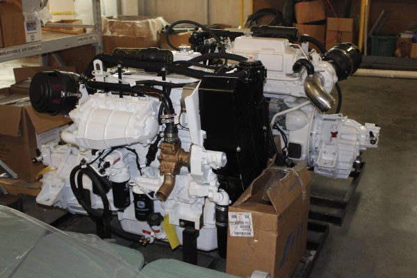
Some very tangible progress! There are now two engines with reverse gear sitting in the shop! I grew up working on John Deere tractor engines and these are the first two JD's I've ever owned.

As much as I hated working on his engines as a kid, I'm sure my dad would be amused to see me buy two of 'em.
 

Attachments

  • Engines 2 2_8.jpg
    Engines 2 2_8.jpg
    112.9 KB · Views: 98
  • Engines 2_8.jpg
    Engines 2_8.jpg
    113.8 KB · Views: 105
Really interesting to watch!

Just for your information, our boat is aluminium too but uses the Strongall(TM) method (translated). Ours is 12mm hull and 6mm superstructure, minimal framing. I presume even more careful welding and skills are needed!

What's so special about the "Strongall" method that warrants a patent? Seems that it is just using aluminum that is about 3x thicker than you would use with traditional construction practices. Seems like a no brainer to me.
 
What's so special about the "Strongall" method that warrants a patent? Seems that it is just using aluminum that is about 3x thicker than you would use with traditional construction practices. Seems like a no brainer to me.

I have absolutely no idea! I can only presume there's something new and patentable since it was granted, but I can't read French or even search for the patent.

As is the case over time, while the patent was created in the mid-1990's or so (25 yrs), technologies and techniques move on and it may not be sensible/practical still, or instead the concepts may be so obvious that the same patent wouldn't be gained today.
 
My limited understanding of what makes this method different is not thicker plates. It is a combination of thicker plates with little (or no) internal framing and carefully place internal bulkheads that provides a boat that is not overall materially different in displacement (despite the plate thickness) but is stronger overall and faster to produce.

Their are some guidelines I recall - such as the waterline length in meters must be equal to the bottom plate thickness in MM - so a 12 meter boat has 12mm bottom plate. There are other guidelines that make up the "method".

I am not expert, but I listen to people who are. My understanding is this method produces a boat with stronger point load - so if you hit something the point of impact is less likely to be dented or damaged than on a traditionally constructed aluminum boat. However, the overall system strength is lower than on a traditional aluminum boat. On my boat (designed to Lloyd's Special Service Craft Rules - I'm sure I'm misusing that term, so any NA's can feel free to correct me) the combination of framing, longitudinal stringers, bulkheads, and plating is such that overall stresses on the vessel are spread among a carefully designed system of mutually supporting "stuff" and therefore are of less overall impact than on a boat that just uses heavy plate with minimal framing. In fact, if I wanted to increase the strength of my vessel, my first step probably wouldn't be to increase plate thickness but decrease frame spacing.

I can believe that Strongall might save construction time and cost - particularly labor hours since I assume there is a lot fewer feet of welding and with heavier plate, welding is easier. But I don't know anyone who produces both (or any NA's who are advocates of both methods) to ask for an unbiased opinion. I'm happy with my decision but I wouldn't look down on a Strongall boat for any reason; particularly if it was built for a specific operating environment and designed by an experienced NA.
 
Last edited:
I made another trip to check out progress. Hull skins are about 90% tacked in place. Once everything is tacked in place they will bring in welding crews to finish the weld-out. It's interesting to watch the process - to keep everything even and avoid twisting or distorting the hull, they keep everything balanced on both hulls. When they hang one skin, they move to the other side to hang the sister skin.

These are shots of the port and starboard hulls from the bow showing the spray chine.
 

Attachments

  • Bow Framing 1 2_14.jpg
    Bow Framing 1 2_14.jpg
    96.8 KB · Views: 95
  • Bow Framing 2 2_14.jpg
    Bow Framing 2 2_14.jpg
    123.7 KB · Views: 102
Last edited by a moderator:
A shot of my port engine room. Everything is tacked into place now. The hand drawn lines show where finish welds will eventually go.

An old habit from my Army life is ask questions and listen. But occasionally ask a question you already know the answer to so you can be on the lookout for BS. The production manager seems to know his stuff and they have a good QC process!
 

Attachments

  • ER 5 2_14.jpg
    ER 5 2_14.jpg
    96.8 KB · Views: 112
These are the awthartship frames forward of the collision bulkhead. They look pretty beefy - I think these guys have seen how I drive boats.
 

Attachments

  • Crash BH 2 2_14.jpg
    Crash BH 2 2_14.jpg
    86.5 KB · Views: 92
A shot of the tunnel with a human for scale.
 

Attachments

  • Tunnel 2 2_14.jpg
    Tunnel 2 2_14.jpg
    104.6 KB · Views: 93
I should get picture of the hull flip today or tomorrow. That's obviously a key milestone event! To celebrate (and because it was a crappy, rainy weekend and I was bored) I did some more arts and crafts.

I hate metal bits and bobs banging around on aluminum, so I've been stocking up on soft shackles. The two long double eye splice pieces are part of the anchor bridle, there are two additional soft shackles and a third thing that too short to use but too cool to throw away. These are all made from 1/4" dyneema so they have around a .025 gazallion pound breaking strength. I highly recommend using soft shackles anytime you don't want a hard shackle or caribeener scratching up gelcoat or making noise.

Hull flip pics to follow...
 

Attachments

  • Rainy weekend project.jpg
    Rainy weekend project.jpg
    99.2 KB · Views: 112
We're a couple weeks behind schedule in the weld up but we flipped the hull earlier in the week.

I talked to a friend whose a multi-generation boat builder in the Chesapeake - he said he wouldn't trust a boat that's built on time. That leads me to my new philosophy - never go to sea in a vessel completed on schedule.

I confess - I'm more concerned they get the hard stuff right and welding is an art that I haven't mastered.
 

Attachments

  • Flip 1 3_6.jpg
    Flip 1 3_6.jpg
    77.5 KB · Views: 110
  • Flip 2 3_6.jpg
    Flip 2 3_6.jpg
    143.3 KB · Views: 107
  • Flip 3 3_6.jpg
    Flip 3 3_6.jpg
    145.3 KB · Views: 112
Last edited:
...and the final shots. I think I see a scratch...
 

Attachments

  • Flip 4 3_6.jpg
    Flip 4 3_6.jpg
    127.7 KB · Views: 100
  • Flip 5 3_6.jpg
    Flip 5 3_6.jpg
    131.4 KB · Views: 107
A couple more pics...house, port side, and view of aft deck...
 

Attachments

  • 3_13 3.jpg
    3_13 3.jpg
    118.7 KB · Views: 91
  • 3_13 2.jpg
    3_13 2.jpg
    130.7 KB · Views: 98
  • 3_13 4.jpg
    3_13 4.jpg
    180.5 KB · Views: 95
Couple shots of the port engine room. One of my requirements was to have engines under the cockpit platform rather than under the saloon sole.

I can't imagine having 2400 pounds of hot engine under my feet in the cabin after dropping anchor on a hot day. Also, I'm hoping to have better noise control since there is a watertight bulkhead between the engines and the tank rooms which are under the cabin sole.

Oh, the two companionways in the third photo are the head (port) and the forward cabin (std).
 

Attachments

  • 3_13 8.jpg
    3_13 8.jpg
    114.5 KB · Views: 101
  • 3_13 9.jpg
    3_13 9.jpg
    135.3 KB · Views: 98
Last edited:
Here's a couple shots of the business end.
 

Attachments

  • 3_25 Bow.jpg
    3_25 Bow.jpg
    135.1 KB · Views: 106
  • 3_25 House.jpg
    3_25 House.jpg
    99.8 KB · Views: 94
The boarding platform...bording platform(?)...boreding(?). Whatever, you know what this is.

Also, a closeup of the welds at the prop pocket.
 

Attachments

  • 3_25 Transom Steps.jpg
    3_25 Transom Steps.jpg
    115.3 KB · Views: 97
  • 3_25 Weld on transom.jpg
    3_25 Weld on transom.jpg
    56.8 KB · Views: 97
A shot of one fuel tank, the starboard engine room, and I have no clue what that third thing is. Maybe a waterproof gronical platform...
 

Attachments

  • 3_25 Tanks.jpg
    3_25 Tanks.jpg
    104.3 KB · Views: 98
  • 3_25 Std Engine Room.jpg
    3_25 Std Engine Room.jpg
    151.4 KB · Views: 97
  • 3_25 No Clue.jpg
    3_25 No Clue.jpg
    118.2 KB · Views: 105
That Front end looks awesome, looks like it could drive right over you while swimming, and you would still have a couple of feet to spare..Looking forward to seeing the finished product....
 
Bkay, thanks for sharing all of this.

I've taken a sudden interest in aluminum as I'm in the process of buying a used racing sailboat built by Kanter Yachts. Will be following your progress with interest.

I admired Jutson's sailboat designs for many years. I'm sure he has vast experience with custom builds. Was this a custom design for you, or were you working from stock plans, or somewhere in between? Sorry if you've already said and I missed it.
 
I admired Jutson's sailboat designs for many years. I'm sure he has vast experience with custom builds. Was this a custom design for you, or were you working from stock plans, or somewhere in between? Sorry if you've already said and I missed it.

Yes, Scott Jutson has done some serious work. I'm amazed at how many different types of vessels he's designed over such a broad range.

When I started this project, I was basing it on an existing design. The boat shown in this photo was a 42' x 13'. I asked to have the same boat, "just a few feet shorter" and with a target speed of 14 knots. I was hoping it might be modest changes to existing files. But in reality, he treated it as a completely new design and started from a blank page.

I'm happy with the direction this project went and I think it will work much better for my purposes that the version in the photo. Although I'm 4' shorter that the boat in the photo, my waterline length is only a couple feet shorter (by my rough calculations) and the space utilization is a little better for me.

One advantage of aluminum (and wood for that matter), every boat can have structural modifications over the previous version.

BTW - the boat in this photo is (or recently was) for sale in Washington. I have no interest other than I've inspected the boat and she is well designed, well built, and the owner was very squared away and let me do an extensive inspection of his boat before I made my decision - so I hope he sells her for a fair price.
 

Attachments

  • WASABI A.jpg
    WASABI A.jpg
    66.2 KB · Views: 254
Last edited:
Progress. They are re-calculating the tentative launch date. Remember this safety tip: Never go to sea in a boat completed on time!

The cutout on the upper right quarter is the air intake for the ER. There will be a louvered vent covering the intake.
 

Attachments

  • 4_1 Brow.jpg
    4_1 Brow.jpg
    116.4 KB · Views: 116
  • 4_1 Port ER.jpg
    4_1 Port ER.jpg
    120.3 KB · Views: 114
Last edited by a moderator:
Wait, now that I look at that second picture, it may be the starboard ER hatch, in which case that cutout in the top right is just a hole they cut in my boat.

Kinda hard to see in these photos with no reference points - but I think I see the prop pocket in that photo, which means that photo is shot looking toward the starboard aft quarter.
 
Here's the value in working with a builder that has in-house design capability. Here's a model of the original NA's helm layout. Not bad, but I was on another boat with this layout and I didn't love it.

It reminds me of an upright piano and I wasn't keen on no protection at the stairs.
 

Attachments

  • Helm Original.JPG
    Helm Original.JPG
    119.9 KB · Views: 82
Last edited:
Here's the highly detailed sketch I sent asking if we could do something a little different:
 

Attachments

  • Helm Sketch.jpg
    Helm Sketch.jpg
    59.1 KB · Views: 76
And here's what I got back the next day. All in all, I like this layout much better. The table is a fold down and sized for chart books.

We still need to check the layout with the wheel and helm chair, but it's clearly an improvement to me.
 

Attachments

  • Helm Revised.jpg
    Helm Revised.jpg
    83.7 KB · Views: 87
I nearly bought one like this that was near complete but buyer bailed on project. Outlaw marine made it in Canada. I always regretted passing it up!
 
Back
Top Bottom