Mainshiptom
Veteran Member
- Joined
- Apr 29, 2018
- Messages
- 79
- Location
- United Kingdom
- Vessel Name
- Naphy III
- Vessel Make
- Mainship 350/390
Hi All from Sunny Kent England
I am a second time Mainship owner, I used to have a Mainship 40 1981 with twin Perkins, Now I have a 1999 Mainship 350 with a single Caterpillar 3116
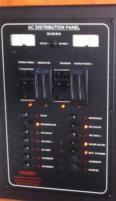
The boat is a 240 Volt, it has two lines in each 16 Amp and I just user one and parallel the two on the fuse control box,
This has been working really well for a few months (bought the boat in May 2018)
Now the parallel refuse to connect looks like something is shorting?
what shall I check for?
So I connect line 1 and all of line 2 fuses are off and when I parallel the parallel switch jumps off.
Thanks in advance
Tom
I am a second time Mainship owner, I used to have a Mainship 40 1981 with twin Perkins, Now I have a 1999 Mainship 350 with a single Caterpillar 3116
The boat is a 240 Volt, it has two lines in each 16 Amp and I just user one and parallel the two on the fuse control box,
This has been working really well for a few months (bought the boat in May 2018)
Now the parallel refuse to connect looks like something is shorting?
what shall I check for?
So I connect line 1 and all of line 2 fuses are off and when I parallel the parallel switch jumps off.
Thanks in advance
Tom
")