Project creep now encompasses all new battery wiring

The friendliest place on the web for anyone who enjoys boating.
If you have answers, please help by responding to the unanswered posts.

questionmark

Senior Member
Joined
Jul 10, 2015
Messages
179
Location
USA
I’ve redone the house wiring and the AC system, but the battery wiring to the primary switch is original. And after wasting most of a day yesterday just trying to run it all down, I’ve decided to rip it all out and start fresh. This whole thing was precipitated by my purchase of an arch and 600w of solar panels to alleviate engine and generator run time on the hook.

The current battery situation is 3 sets of Trojan T-105s, sort of set up in the “2 for house, 1 for start” type configuration, except there’s tons of random stuff just tapped off in random places (of course, unfused.) The two sets for “house” have a 1-2-off switch mounted between them. That runs through an unlabeled fuse through a run of unidentified wire and to another 1-2-off switch to join with the “start” bank (on position 2) which is run with what looks like welding cable (either way it’s black for positive.) I’ve just been running everything in the “all” position and pretending it’s fine because it works.

The wiring is a hodge-podge of different gauges and types. No two of the battery connects is the same, neither in gauge nor wire type nor length.

So, my current plan is this:

All new battery cables with proper crimps and heat shrink. Each bank will run to an “on-off” switch (through a 150 amp fuse at the battery), which will then join at a covered primary bus bar. This will give me the ability to isolate any one battery pair should there be a problem (bad cell or whatever.) Phase 2 will involve a dedicated starting battery with an echo charger, but for now I’ll just start off the one big bank.

All charging will land on the primary bus bar. Alternator is new (blew up another rebuilt auto one so broke down and upgraded), and so is the 100amp charger (Magnum inverter/charger.) The arch for mounting the solar arrived today, so I’ll have 800w of solar (200w now) when I’m done. That’s 2 each of 300w panels with their own controllers, and my current 2 each 100w panels in parallel to a third controller.

All cabling will be 2/0 except the run from the inverter/charger, which will be 4/0. I have a nice hydraulic crimper for the ends and a fair amount of experience in using it. I got a smoking deal on two spools of Ancor 2/0, so even though the math works out for 1 gauge, it was cheaper to go this route. Plus I already had the terminals in 2/0 so that saved even more.

House usage has been between 85 and 100 amp hours per day. I am three reading lights away from being all LED lighting, and I’m adding a deep freezer unit which should add another 40-45 amp hours depending on ambient temperature. I’m estimating 150 amp hours per day draw for planning.

The current plan is to cruise down to the Sea of Cortez this winter. We’ll need to be back in a marina every couple of weeks because my son’s school will require him to check in via video-conference regularly. So figure two to three week cruises at a time. The longest we’ve done so far was two weeks, and that’s why we ordered the freezer...

Any advice, or anything I’ve missed? I’ll try and take pictures, but sometimes I get on a roll and forget.

Josh
 
Last edited:
Sounds like you have a good handle on the situation. I, therefore suggest you go to Lithium based batteries to challenge yourself. :hide:

Or, at least do a wiring diagram on Visio or something for us to poke at.
 
Never a bad choice to go oversize on battery cable. Sometimes it is really easier to just start over. My boat had a really strange charging setup so I understand where you are coming from. Good luck.
 
Greetings,
Mr. q. Project creep?


200.gif


You've just discovered my middle name. I've come to realise that any project is simply an exercise in adding to "the list". As to your last sentence: "...on a roll" is a GOOD thing.
 
Is that 150 amp fuse before the starter?
Also check what fuse the Magnum requires between bank and inverter.
 
Fusing the start battery will be a mistake unless its huge - 150 amps is not enough.
 
Fusing the start battery will be a mistake unless its huge - 150 amps is not enough.


Why? The upgraded starter for my motor is rated at 3kw, and the standard one at 1.7kw. Those are worst case numbers, so I should easily be able to start the engine on two of the three sets. As far as I can tell from the data sheet, it seems the 1C current for the T105 is 250amps, so I am hesitant to fuse above that number.

The max rating for 2/0 cable with a 105C temp rating in an engine room, where these will live, is 270amp. I could see bumping up to 250 amp fuses, but not above.

Even that seems like overkill because there’s a bunch of 2 gauge wiring that’s there now. The only large draw items I have are the inverter (267a for five second surge), the SSB (25a transmit max carrier), and the horn (15a when sounding.) Assuming I don’t use the microwave and the starter simultaneously, I should easily be under 300a draw, and way below 450a.

I guess there really isn’t a reason not to go with the 250a fuses, as it still protects the wire. I’ll go for it.
 
Would think you need at least a couple of more batteries.


Why? Before I added the first two solar panels I could easily go three days in between charging sessions. We run the engine every other day for hot water, so we end up charging about 40-45 amp hours during that. I noticed after I added the 200w of solar I was putting back about half my daily draw just with the panels.

I’m adding another 600w of solar and a freezer. It should be total overkill, even when it’s overcast. At 40% depth of discharge I’ll have two full days of discharge capacity at worst case. Why would I need more?
 
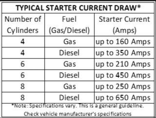
The moment you push the starter button the current inrush is significantly higher than 150 amps until the motor reaches its operating speed. You haven't mentioned your engine type, but here's something for you to digest.

That's why.
 

Attachments

  • Screen Shot 2018-08-23 at 8.44.13 PM.jpg
    Screen Shot 2018-08-23 at 8.44.13 PM.jpg
    122 KB · Views: 79
Last edited:
I put 300 amp fuses on a previous boat but that boat had gas engines. I couldn’t start my diesels on 300 amps.
 
" 3 sets of Trojan T-105s, sort of set up in the “2 for house, 1 for start” type configuration"


I thought the T105 was a 6v golf cart deep cycle battery , seldom a choice (even paired) as a start battery?
 
" 3 sets of Trojan T-105s, sort of set up in the “2 for house, 1 for start” type configuration"


I thought the T105 was a 6v golf cart deep cycle battery , seldom a choice (even paired) as a start battery?


It is. And it usually isn’t...

The project is on hold for a few days as the fates have decided that instead of having days off to work on the boat, I really need to work the next five straight. The good news is that this will fund the project and the addition of a dedicated start battery. It’s the usual story, when you have the time there’s no money, and when you have the money there’s no time...

So the new plan is to use the three sets of Trojans for the house, with 250 amp fuses on each. A dedicated starting battery with an echo charger. I’m thinking a group 31 battery. I can reuse the switch that is currently in between two of the sets of Trojans.

I guess I’ll be able to run the microwave and start the engine after all...

Josh
 
So, the fates decided to really delay this project, as I got deployed up to Northern California for almost three weeks for work. But I got back home yesterday and back to boat work today. It was a pretty good day.

I laid everything out to make sure I had what I needed. With the exception of leaving the new battery monitor at home, everything is here. I measured out the longest of the three positive battery cable runs, and then made all three cables that length. I did the usual label and clear heat shrink, so each end is labeled with what’s on the other end.

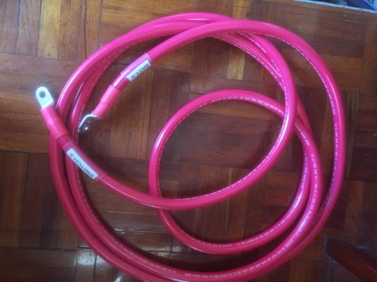
IMG_0351.jpg

Here’s one of the finished cables. The hydraulic crimper got a workout today, as the interconnects between the 6V batteries were crap, so I made new ones. I also made the short cables that will go between the switches and the positive bus bar. Everything got glue lined heat shrink as well.

Then I started removing the old wiring. I disconnected the battery positives and started back pulling. And that’s when I discovered that all of my loads were on the wrong side of the one existing fuse. Turns out that everything was on the supply side, and the only wire on the fused side was the alternator. It looked right at first, and even the surveyor missed it. Got lucky on that one.

I ended at a good stopping point this evening. I have tomorrow off as well, so my plan is to remove the old alternator, alternator controller, and the rest of the wiring. I’ll mount the new switches and bus bars. I did a dry run mount of the inverter and I really don’t like it under the stairs. I think I’m going to try moving it into the storage locker (used to be the shower.) it’s the same cable length away, and a bigger air volume for cooling. So hopefully I’ll get the charging system installed, although that’s a pretty ambitious day.
 
"and the only wire on the fused side was the alternator. It looked right at first, and even the surveyor missed it. Got lucky on that one."

You bet a blown fuse while charging usually would cost the alt its diodes .

Be sure to only use rotary switches with field cut offs , so a bad move wont cost the alt.

I have the one wire 12SI Delco alternators, I think if the single wire comes disconnected nothing will happen to that alternator as it becomes unloaded. I also think some type alternators are more likely to self destruct. I know the old Chrysler car alternators were like that, they fried instantly if disconnected from the battery, but my knowledge is going back a few decades on that.
I have 80 amp blue sea red fuse boxes on the 80 amp alternators. There is no interrupting rotary switch, they are hardwire connected at the rotary switch to the lug that goes to the batteries. I have never seen these alternators need to output more than 50 amps by looking at the ammeters. And they are reliable. The inline fuse protects the wire if it inadvertently shorts to ground. I suppose it also protects the alternator from a dead output short if running.
 
Last edited:
Update as I take a little break from boat yoga in the engine space...

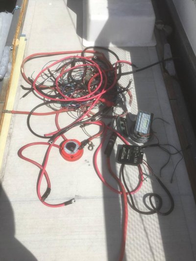
So far, this is the wiring that I’ve removed today:
IMG_0356.jpg
Actually, there’s a bit more than that now, as I took that shot before lunch and before I pulled the last battery positive run.

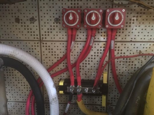
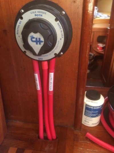
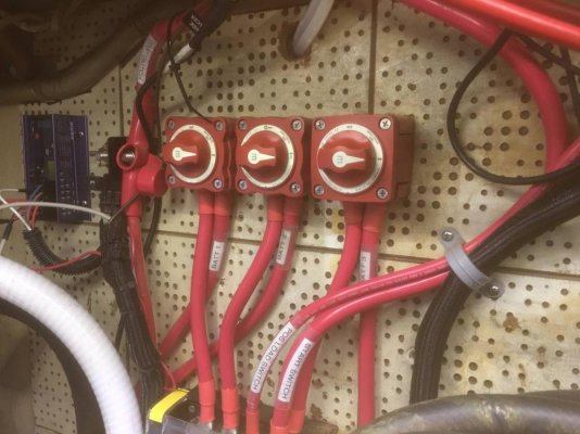
Here’s what the positive switch/ bus bar looks like now. I haven’t done the cable management yet, so that’ll be cleaned up. I’ve also been taking the time to remove the sheet metal cable anchors that came original from Taiwan, and I’ll be replacing them with proper cable management.
IMG_0358.jpg
That one little guy heading off to the right is the original supply for the house panel. I’ll be replacing that shortly.

Now I’m going to try and get the negative cables made before I have to leave. Doubtful, but I’m off again on Saturday, so I should be able to have house power back by then. Luckily the fridge is dual power so the beer stays cold...

Also, if anyone wants the Heart Interface and alternator regulator, they’re free (you pay shipping or pick up in SB/Channel Islands) to a good home. Both the battery monitor and regulator shunts are included. Everything works, I’m just going with a different solution.

Josh
 
Greetings,
Mr. q. Atta boy. Looks pretty sweet. Nothing quite as satisfying as cleaning up and upgrading boat wiring. I look forward to pictures of the finished masterpiece.


In spite of the fact that I'm weak on electrics I usually have no problem replacing one wire at a time which is what I did with a previous 1974 MT. I ended up with two, one cubic foot boxes, packed fairly tightly, of redundant/poor/undersized wiring. An unwanted legacy from several DPO's.


Seems I'm going to have some time this winter so I may attack our current vessel's rat's nest...


200.gif
 
Nice work, Josh! You're rebuilding the electrical backbone of your boat. That will make a huge difference with all the upgrades planned.

FYI, I can start my Perkins 4.236s with a 300A fuse no problem. Each starts from the same single Gp 31. Since it charges from the port alternator, I always start the port engine first and verify the oil press and charge before second (stbd) engine start.

YMMV.
 
I once tried to measure the starting current on a small two cylinder Yanmar with a 200A clamp on meter. It pegged the meter, not just inrush current- it stayed pegged while cranking.


If an alternator that is still turning is quickly disconnected from its load, the voltage will momentarily shoot up and it will fry the diodes. All marine 1,2,all,off switches are make before break to help avoid this. Field current disconnect switches as FF mentioned are probably better.


David
 
Today was HUGE! Firstly because I actually got the day off work. I was supposed to have five days off this week before I rolled into another work segment, but that got nuked to about a day and a half, and today was the day.

But more importantly, the battery cabling, monitor, and inverter/charger ARE IN!!!! We have lights again. And pumps. And it’s all fused properly.

The charger is a Magnum Energy 2412. It’s connected to the batteries with 4/0 cable. The new battery monitor is a Victron 712 (with Bluetooth.) I ordered Victron MPPT controllers to work with the new solar panels, so since I’ve been working so much lately I bought myself a present. The old monitor will go on the start battery, which is sitting on the salon floor waiting for my next day off.

The Bluetooth is totally a toy but since I’m such a nerd anyway I love it. The solar controllers all have it, too. It sure felt good to fire it all up and see it reading volts again.

I didn’t think I was going to finish, but it turns out that when I built the AC panel a while back that I dropped the inverter input and output lines onto a terminal strip and jumped them together. I forgot I did that, so instead of having to rewire the switch and load breakers, I just popped off the jumpers and landed the 10/3 wires onto the strip. Took about 15 minutes to label and terminate them. I think I’ll thank myself with an adult beverage tonight...

Im supposed to be off again on Friday, so I plan to route and properly secure all the cables. I’ll take some pictures then.

It’s just been a frustrating week or so, and it feels so good to finally see progress. Now I just have to mount the starting battery, cable it in, install the 1-2 switch for emergency house bank starting, install the charge relay, install the old battery monitor, install the new alternator and controller, install the solar arch, install and wire the solar panels, install the MPPT controllers, and maybe even use the boat if there’s time...

Josh
 
Managed a half day today and a half on Friday. Even though it was two halves, it still didn’t equal a whole. I did manage to figure out where I’m going to place the start battery, and I ran the positive cabling for it. I also mocked up the duo-charge location and figured out the cable routing. Turns out that I’m out of 10 gauge wire, so the final runs will have to wait.

I’m planning on mounting it to the underside of the salon floor. There aren’t any indicator lights or anything on it, just a magnetic switch for programming, so I don’t need to mount it in view. It’s convenient and it fits well, so unless anyone can think of any reasons why not, I’ll mount it on Thursday.

I took a couple pictures but they don’t really convey much. Here’s about the only one that even remotely turned out: IMG_0377.jpg

I’m still on the fence about whether to install a master switch for the 12v house system. I repurposed the old one shown above as the starter on/off/selector. I have the three individual battery switches before the main positive bus, I think that should be enough. The bilge pumps are going to be wired direct, the ignition is moved to the start battery (debating adding a switch on the dash to select either start or house for ignition) so the only thing that would be switched would be the 12v panel. That panel is new(er.) In our normal practice I’ve just always left the 12v switch on, so I feel ok leaving it out. Anyone have any thoughts either way?

I have two days off in a row starting Thursday, so my goal is to have an engine that starts and cabling secured. Fingers crossed for that...

Josh
 
Just a quick update to say that I’m pretty stoked because my boat starts again...

And that after I removed my head from my keister I realized that a switch on the dash for ignition was pretty idiotic. I just back traced the ignition switch and found it landed on the engine terminal strip (duh!) so I just ran a wire from the common post on the battery selector switch to the ignition terminal. Now it’s automatically powered by whichever bank is selected. One of my old, now retired, bosses used to say, “Lessons in humility are right around the corner.” This is a nice reminder that I’m not necessarily as smart as I sometimes think I am...

Josh
 
Glad it's all falling into line for you. Boat electricity can be a tough issue to sort out. Mine was a mess when I got her. I recabled my loads with 28V/3000A aviation ground power unit cable (properly fused) that has wire so fine it's more like hair than wire. It gave me a chance to design my electrics from the ground up (pun intended) and I enjoyed the challenge. In my way of thinking, proper system configuration and monitoring is important.

My aviation experience taught me to appreciate systems that allowed total flexibility with charges and loads. IMO, one charge source should be able to provide power to all battery banks and any bank should have redundant power sources. I can charge house or start banks from either 1 of 2 alternators, my gen and/or my single bank shore charger. I can power either or both house or start loads from either or both battery banks. If I need to isolate all house or start loads, I can do so with 2 switches in easy access of the lower helm located outside the ER door.

IMO, many boat mfr's don't help by their stock system design that uses the start cable to provide both start or house load and charge from the alternator. It's challenging to separate load from charge when the electrons flow both ways in the big cable.

At the sacrifice of my helm analog ammeters, I recabled to provide alternator charges directly to the batt banks; port to start, stbd to house. I added a SOC meter to replace the analog ammeters.

I encountered an issue in July when I was glad I had this capability. Long story, short....I had an erroneous indication of a 600A house bank short during a period of high seas and 'water infiltration" into my FB helm console. The drips shorted my SOC, rendering the false alert. With old mechanical diesels, I was able to switch off ALL 12V loads in my attempt to isolate the suspected short. When my battery voltage remained stable and water dripped on my hand, I knew I had shorted the monitor. Switched the 12V power back on and continued without an issue.

I'm a big fan of 1-switch isolation withing easy reach, ie. not in the ER.
 
That sounds like quite the experience. Thanks for the advice.

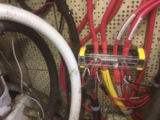
I’ve got my alternator landing on the positive bus bar, along with the AC charger and the solar controllers (more on those later.) each of the three batteries has its own isolation switch, so if one really wanted to it is possible with this design to destroy the alternator by turning off all the batteries. But you’d have to really want to as they’re in the engine space. It is a single switch in the salon to turn off the ignition power and starting system.

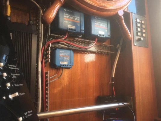
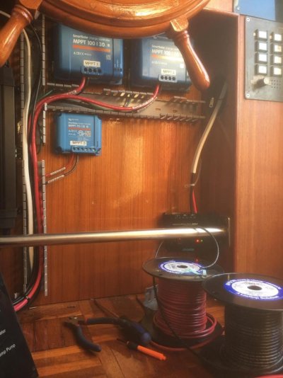
I did a bunch of wiring cleanup today, and installed the Duo-charge and wired up all three of the new MPPT solar controllers. A quick read of the install manual said the largest wire they take is 6 gauge. I have a crimper die for that, so back down to the chandlery for wire and lugs (at least I measured first this time.) I think it turned out pretty good:
IMG_0389.jpg IMG_0390.jpg

That black box hanging is the old PWM that came with my first two 100W panels. I’m going to rewire them into the smaller controller, and the two larger ones are getting a 300W panel each. I originally ran 8 gauge duplex up to the flybridge for the solar, but it’s total overkill. So I’m going to pull it and re-purpose it for the new deep freezer, and run new 10 gauge up to the panels. I have to pull 2 new sets for the new panels anyway, might as well make it 3. The best part is all those wires will take up less space in the chase than the current big duplex wire.

But that has to wait till Friday...

Josh
 
I'm a big fan of 1-switch isolation withing easy reach, ie. not in the ER.


I’ve been thinking a lot about this. I have about an hour commute and this morning I spent every second of it pondering this. Basically trying to justify in my mind why I don’t need to add a load switch, and in that time I couldn’t think of even one compelling reason not to.

So I’m going to do it. I’ve got all the parts and wire laying around, so I’m going to take your advice and split the charging bus and load bus and throw a switch in between. Added bonus is that with one additional cable I’ll be able to run the house loads off the starting battery in a dire emergency. I’m thinking I’ll put the switch down near floor level in the settee, where it’ll be out of the way yet accessible in a pinch. I’d love to put it next to the ignition switch but the cabling just doesn’t work as well there.

Thanks again for the advice.

Josh
 
I’m so close to putting a wrap on this project, I can taste it. I finally escaped work this morning and got a boat day. I took an unfortunate 50 hour detour through Malibu and I’m still trying to recover. I’m not 25 anymore, and I just can’t catch up on rest as fast anymore. Especially when we’re back in the city and getting up at least four times a night...

At any rate, I’m in the “wire management” phase now, and it’s really coming together nicely. I’ve also knocked out a ton of ancillary stuff while this major work has progressed. Sadly the pictures don’t do it justice, but the difference is remarkable...

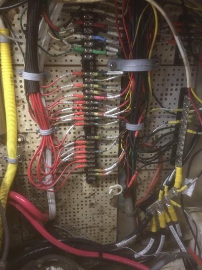
Here’s the “after shot” of the forward bulkhead where the old terminal strips were. I’ll try and find some older “before” pics, but it would be hard to compare because the wiring here was such a rats nest you couldn’t see the strips anyway.
IMG_0482.jpg
There’s still work to be done, and I still have to terminate that macerator wire, but I’m happy with how it’s looking.

Here’s the “after shot” of the forward bulkhead on the port side where I landed the positive bus and new alternator controller.IMG_0483.jpg
Those two cables heading through the bulkhead is pre-wiring for the chest freezer. I bought an AC/DC chest freezer which I’ll be installing after I finish this and the solar. The wiring is all ready to go so it should be quick once I figure out the flange issues (as in they don’t make one, so it’s off to the metal shop for me.)

This isn’t a great picture, but until I cut out the port fuel tank and reroute the drain and raw water hoses it’s kind of a mess.
IMG_0484.jpg
Everything seems to be working, so that’s a plus. I wired the switch in for the DC load cutoff. I messed up the drill so now I get to fab a cover plate. Luckily I still have access to the laser cutter. I have to fab new dash and instrument cover plates, so I’ll do those all at once at some nebulous later date.

I’ll probably go back to my omnibus thread for a bunch of the new stuff that isn’t directly battery cabling. And I’ll do a new thread for the chest freezer, because I’m going to need some major advice along the way on that one.

Josh
 

Latest posts

Back
Top Bottom