Davis 42 Light Refit / Rehab

The friendliest place on the web for anyone who enjoys boating.
If you have answers, please help by responding to the unanswered posts.

fractalphreak

Senior Member
Joined
Jun 23, 2018
Messages
318
Location
United States
Vessel Name
Northwest Dream
Vessel Make
Davis Vashon 42 Trawler (Defever design)
Here is the refit thread I promised after announcing we are trawler owners. To recap, the boat is a 1980 Davis Vashon 42 trawler that is a Defever design or copy. It was built by the Sei Yen Enterprise yard in the east of Taipei (I think) near Keelung. The boat is 42 x 14 with 4'3" draft and displaces approximately 30,000 lbs. it is documented and has been for most or all of its life. I believe we are the fourth owners. The first was the owner of Crow Roofing in Seattle - the only record I have of his ownership is his name on the engine warranty cards I have. I have surveys, receipts, and other documentation from the other two owners. The boat has had a lot of professional yard and marine service work over the years. Many systems have been upgraded, some have not. The engines, transmissions, and genset are from when the boat was built. Some systems, like most of the domestic water lines, are original (copper!) Others, like the heads, have been replaced with newer (they are freshwater electric flush going into the factory fiberglass tank that is integral with the hull and stringers aft of the engine room.

Our price range / financial means and my skills put us in a position of buying a well used boat with some necessary projects. We set aside a full third of our available funds for repair, refit and upgrades and then factored in what those costs might be for each boat we looked at to find one that made sense.

(My spreadsheet to track all of the myriad details went from column A to AT, and was basically a color coded checklist of features, price, design, maintenance needs, hidden risks, and what upgrades the boat would need to match our desires.)

So we bought the boat, knowing the following repairs and maintenance would be needed - since we'd set aside the cash for it they are happening now and quick. We want to turn the boat around and begin enjoying it next cruising season (or even this winter!)

Initial Major/Priority projects for boat preservation/usability

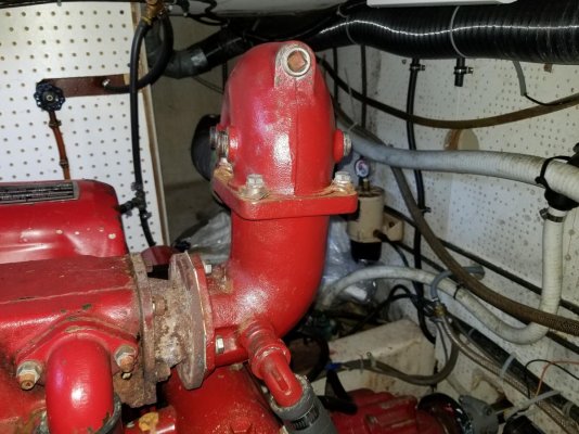
1 - Exhaust elbows - non-standard, causing likely salt water drip back to end of exhaust manifold.
20180905_185831.jpg

2 - Batteries - House batteries, while high quality, are at end of life

20180728_134303.jpg

3 - Windows - show signs of past leak activity. Appears PO had put some sealant on exterior without disassembling and truly rebedding.

IMG_3378 crop to window.jpg

4 - Aft house deck - shows signs of weakening. Surveyor was not too concerned except for one area with some high moisture, but deck is misshapen and has some flex to it when a bulky individual (me) steps or bounces on it too heavily. We bought boat anticipating a complete aft house deck recore job. As we anticipate having the tender on the aft deck while in the marina (we are right at the tipping point from one dock size to another, and long term keeping it on the aft house top will keep our costs down.)

20180728_161906.jpg

5 - Teak trim around base of house at deck coming loose in spots, needs to be removed, rebedded, refinished.

IMG_3359 deck trim close crop.jpg

There are a myriad of smaller projects, but these are some of the first big ones to tackle. Our work list between survey findings and our own findings and upgrades is about 175 items.

The above are our initial major projects.

Battery Bank
The house batteries were very nice Northstar batteries, but at 10 years old and always running a decently large fridge/freezer they could not keep up with the boat aH requirements. The house bank consisted of two of these batteries. My computations of the boat's equipment and our own needs put our minimum USABLE bank at 200-210 aH per day, which with good AGM batteries would require at least 300-350 aH for some longer life, and with lead-acid at lest 500 aH. Cost wise I just couldn't do $1,800 to do AGMs and instead have gone with paired GC-2 lead acid. My 630 aH bank will end up costing about $650 with tax, plus another few hundred for cabling and tools to make said cabling (our 2,000 amp Magnum inverter/charger has us at 2/0 cable for the house.) My projected use of the bank has us using approximately 1/3 per day, which with proper water topping off should give us good life. The bank is in battery boxes in between the engine stringers and under false floor panels for (relatively) easy access. I made sure all the cables for pairing and paralleling the pairs are out of the way of refilling water. This project is 75% complete. I still need to buy and install two more batteries. I already have the cables made, and have to do the install. My apologies for not having photos of this, but we went ahead with the bank install our third day on the boat as the old batteries couldn't make it through the night with our fridge and my CPAP!

Next post with photos, will be about the engine exhaust elbows...
 
Last edited:
Exhaust Elbow Subproject

Since we signed the acceptance paperwork I've been working on plans to revise the exhaust. I didn't like the looks of it, neither did the surveyor. Interestingly enough, the mechanic liked the design, which makes me wonder if he or his company originally installed it! He was critical enough of anything else he found at issue on the engines, so I SOMEHWHAT trust him...

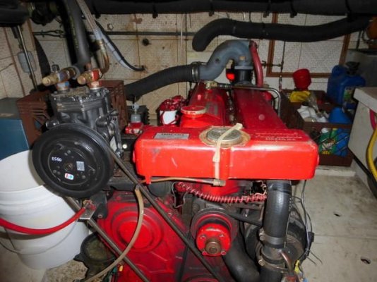
Here's a photo of the whole setup as it looks on the port engine. Its a massive piece of iron. Yes, I know the hanger is broken - its coming off anyway and we'll install whatever is needed after the new stuff is added.

View attachment 80950

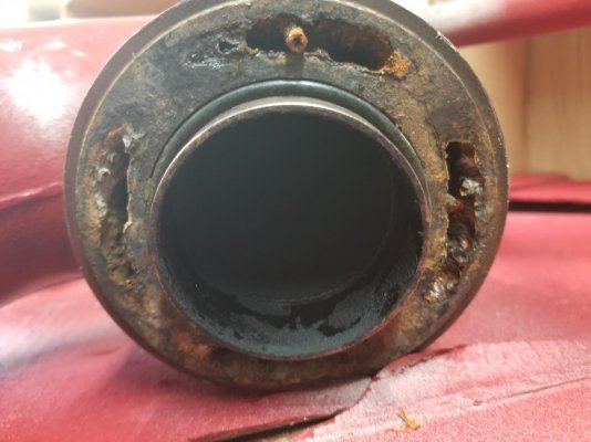
My research on Lehman (and any) exhaust system is you don't want saltwater making it back into the exhaust manifold. My first view of the boat showed that appears to be in fact happening, as there is substantial corrosion around the the adapter that allows the non-standard exhaust to bolt to the Lehman exhaust manifold, and even what looked like dried up salt.

In this closeup of the stbd engine you can see all the corrosion, the adapter, and there is even rust drips down from the mating surface of the manifold and adapter onto the heat exchanger.

20180905_185836.jpg

My initial thoughts were to (obviously) put the correct exhaust mixing elbows that were designed for the engine, and then redesign (as needed) the rest of the exhaust system from there. The rest of the exhaust as I found it is 3.5" hose straight back down the sides and out the transom, to include 1 1/2 - 2' extensions past the transom, likely to keep soot off the dinghy. Nothing to prevent any siphon. The boat is a little loud, as you would expect from unmuffled straight pipes.

I have seen and heard some Lehman powered boats that have water-lift mufflers and noted they do moderate the sound somewhat. I decided to add these to the boat, and have chosen Vetus NLP (HD) 90 waterlock. The HD versions are made out of a special material and have a maximum sustained temperature rating of 482F. The model 90 is sized to accept my 3.5" exhaust hose and rated for up to 120 HP. Just to be sure we aren't going to fry anything, I also ordered an engine alarm kit that watches engine temp, raw water flow, oil pressure as well as bilge water level and has a fire sensor. (I chose the one with raw water flow rather than exhaust gas temp as I figured a loss of flow would indicate trouble a few seconds quicker. I hope that is a valid thought.) I'll put the raw water flow right before the mixing elbow injection point, to try to capture flow up to the last possible measuring point.

After the boat was in a dry storage yard (we are there until a spot opens at our chosen marina, probably late this year) I carefully measured our exhaust relative to the boat waterline. As it turns out the bottom of the exhaust is only about 3 inches above the WL, less than what is safe. SO I added an anti-siphon loop in the design to go right at the elbow.

We've started taking the exhaust apart, and found that it is a swivel design with an o-ring seal in the middle. Additionally it looks like the cooling water passages are compromised and its probably time for new anyway. I don't know how you would get all the passages clear on that massive piece of iron anyway.

20180914_174544.jpg

When I checked the part numbers, I found the entire assembly is a Barr creation for a gas Chrysler V-8. AND found that they are designed for a smaller exhaust hose, so there is a short piece of another hose inside the 3.5" hose acting as another adapter!

20180914_174535.jpg

Needless to say, we are prepping for putting it all together and hope for a long lasting decent solution to the problem. (I found where Bob Smith from American Diesel recommended regal red for these engines, and since I painted my workbenches that color in 2001, I thought that's what I'll do! Here is 5 or 6 coats, Josh lost count!

20180912_162611.jpg

More of the parts will be arriving Monday, and over the next week or two we'll work on dry fitting everything. We'll have to build a platform to sit immediately out from the outboard engine stringer to mount the waterlock on, epoxy that into place and paint it. We won't do the final install until we have some fuel tank work done (install clean outs, clean, polish fuel) so we can have better access to the aft end of the tanks.) As we proceed I'll update you all on how it goes.

A question I have is do similar build trawlers put goosenecks at the stern to keep water from coming up the exhaust pipes? In reading and researching, I see they are a common recommendation on a proper exhaust system, mainly to keep (I believe) seawater from coming in the back way. Do any of you have these?
 
Last edited:
Good move restoring the exhaust angle to OEM. You probably discovered they come in 2 diameter sizes.
No preventers on our exhausts, no issues in 8 years. Our mufflers are fiberglass replacements locally made (by Foreshore Marine in South Sydney, for Aussie locals). Of interest, a marina neighbour has right angle exhaust extensions at the waterline, so that water hitting the stern hits pipe not open exhaust. That boat is used for game fishing and would be regularly backing down while hooking up.
Don`t stress about the Lehmans too much, they are rugged beasts.
 
Typically you would put the muffler discharge line as far up as available space allows then slope it downward towards the overboard discharge. Photo is from a Great Harbour N37. Also, if you go with this type installation you will need to add a vented loop since the raw-water will now be dumping into the exhaust below the waterline. That element is also visible in the photo on the bulkhead.

Since we signed the acceptance paperwork I've been working on plans to revise the exhaust. I didn't like the looks of it, neither did the surveyor. Interestingly enough, the mechanic liked the design, which makes me wonder if he or his company originally installed it! He was critical enough of anything else he found at issue on the engines, so I SOMEHWHAT trust him...

Here's a photo of the whole setup as it looks on the port engine. Its a massive piece of iron. Yes, I know the hanger is broken - its coming off anyway and we'll install whatever is needed after the new stuff is added.

View attachment 80950

My research on Lehman (and any) exhaust system is you don't want saltwater making it back into the exhaust manifold. My first view of the boat showed that appears to be in fact happening, as there is substantial corrosion around the the adapter that allows the non-standard exhaust to bolt to the Lehman exhaust manifold, and even what looked like dried up salt.

In this closeup of the stbd engine you can see all the corrosion, the adapter, and there is even rust drips down from the mating surface of the manifold and adapter onto the heat exchanger.

View attachment 80944

My initial thoughts were to (obviously) put the correct exhaust mixing elbows that were designed for the engine, and then redesign (as needed) the rest of the exhaust system from there. The rest of the exhaust as I found it is 3.5" hose straight back down the sides and out the transom, to include 1 1/2 - 2' extensions past the transom, likely to keep soot off the dinghy. Nothing to prevent any siphon. The boat is a little loud, as you would expect from unmuffled straight pipes.

I have seen and heard some Lehman powered boats that have water-lift mufflers and noted they do moderate the sound somewhat. I decided to add these to the boat, and have chosen Vetus NLP (HD) 90 waterlock. The HD versions are made out of a special material and have a maximum sustained temperature rating of 482F. The model 90 is sized to accept my 3.5" exhaust hose and rated for up to 120 HP. Just to be sure we aren't going to fry anything, I also ordered an engine alarm kit that watches engine temp, raw water flow, oil pressure as well as bilge water level and has a fire sensor. (I chose the one with raw water flow rather than exhaust gas temp as I figured a loss of flow would indicate trouble a few seconds quicker. I hope that is a valid thought.) I'll put the raw water flow right before the mixing elbow injection point, to try to capture flow up to the last possible measuring point.

After the boat was in a dry storage yard (we are there until a spot opens at our chosen marina, probably late this year) I carefully measured our exhaust relative to the boat waterline. As it turns out the bottom of the exhaust is only about 3 inches above the WL, less than what is safe. SO I added an anti-siphon loop in the design to go right at the elbow.

We've started taking the exhaust apart, and found that it is a swivel design with an o-ring seal in the middle. Additionally it looks like the cooling water passages are compromised and its probably time for new anyway. I don't know how you would get all the passages clear on that massive piece of iron anyway.

View attachment 80945

When I checked the part numbers, I found the entire assembly is a Barr creation for a gas Chrysler V-8. AND found that they are designed for a smaller exhaust hose, so there is a short piece of another hose inside the 3.5" hose acting as another adapter!

View attachment 80946

Needless to say, we are prepping for putting it all together and hope for a long lasting decent solution to the problem. (I found where Bob Smith from American Diesel recommended regal red for these engines, and since I painted my workbenches that color in 2001, I thought that's what I'll do! Here is 5 or 6 coats, Josh lost count!

View attachment 80947

More of the parts will be arriving Monday, and over the next week or two we'll work on dry fitting everything. We'll have to build a platform to sit immediately out from the outboard engine stringer to mount the waterlock on, epoxy that into place and paint it. We won't do the final install until we have some fuel tank work done (install clean outs, clean, polish fuel) so we can have better access to the aft end of the tanks.) As we proceed I'll update you all on how it goes.

A question I have is do similar build trawlers put goosenecks at the stern to keep water from coming up the exhaust pipes? In reading and researching, I see they are a common recommendation on a proper exhaust system, mainly to keep (I believe) seawater from coming in the back way. Do any of you have these?
 

Attachments

  • DSC05958.jpg
    DSC05958.jpg
    93.1 KB · Views: 177
If the exhaust run is long enough and high enough, no gooseneck is needed. If anything, the high spot should be at the waterlift muffler and have a long, downhill run out the transom.
 
From your picture (#1 in post #1) it looks like the water attachment is to a proper elbow that is mounted upside down, so there is no opportunity for the water to simply run down the exhaust pipe, should there be any leakage while there is no exhaust pressure driving it into the pipe. If this location is less than 12" above the WL, you should think about putting a vertical riser on before the mixing elbow. That would give you a downhill run after the mixing elbow, to the water lift muffler, which will then have another downhill run to the exit.
Your avatar picture shows a design similar to my own, so I expect about the same elevations in the ER and at the locations of the exhaust elbow and muffler. Mine tilts downwards from the engine attachment (no need for any vertical riser) and the muffler sits at the height of the stringers to which the engine mounts are attached.
In mine, the WL is only a few inches above those stringers, so I get about 24" above the WL to the top of available space in the ER. The injection point is at least 14" above WL. If you have any thru hull fittings that you can see on the outside, that will give you an accurate measure of the WL for inside registration.

I am presently replacing the sliding window in my aft head, as I leaned against the glass with my knee this summer and cracked the glass.
I had a cracked front window that I replaced in June, so I am familiar with the way those were built. I have done a few of the sliders already, but that was many years ago and I couldn't quite recall the difference from the construction of the fixed windows. Many Taiwan Trawlers have had problems with leaks from the sliding windows, so your complaint is not unusual. The method of construction is to blame. In mine, the frame around the upper 3 sides is bullet proof. On the fixed windows that is true of all 4 sides, as they are the same. On the sliders, not so much. The sill is designed to fail. The sill is made of a 1/4" x 1 1/2" strip of teak laid on top of the plywood that lines the inside of the Deckhouse Fibreglass wall. A little 5200 sealant may have been under the track originally, but after many years there is little trace. No drain holes were drilled in the track to allow rainwater to exit to the outside. There are rain channels in the teak moulding that frames the window on the outside, but those may have been added by a PO, as the saw marks are still visible. In my other repairs of slider leaks, I have made a fully water tight sill, using a thick bed of 5200, which has stood the test of up to 20 years. This time I may try a piece of "Blueskin" window installation membrane under the track.
Below the leak, naturally, the plywood has been wet for years, so whether rot has set in or not, I will be replacing some of it. Trouble is that it is bonded to the outer FG, so the wet part will have to be ground off, then a mix of epoxy and thickener troweled back on to fill. Then a new interior finish will have to be attached. In my head, that is white Formica, so will look the same as before.

Good luck with your projects. Keep the pictures coming.
 
Last edited:
sounds like you have a solid plan for your boat. you might want to check Seaboard Marine-sbmar.com. tony has some very good info on diesel exhaust systems with many repowers under his belt. good luck


jim
 
As madoc1 mentioned read Tony at Seaboard Marine articles on marine exhaust design, you will learn a lot. Then call these guys, they're local and know what they're doing.
National Marine Exhaust, Inc.
3710-B 136th Street NE
Marysville, WA 98271
 
If the exhaust run is long enough and high enough, no gooseneck is needed. If anything, the high spot should be at the waterlift muffler and have a long, downhill run out the transom.

(and bglad) you both make a great point. I'm looking at how high I can get that pipe before it heads aft. I haven't measured it, but I'm guessing the exhaust from from the aft engine room bulkhead is 14 feet or so.

I have to climb in there and measure the height, but it looks like I should be able to get 10-12 inches higher than the run. In this pic you can see my space constraints. I need to get in there and figure all of the geometry, but for perspective the waterlock will be just out of the shot below the pile of absorbent pads, and most likely 1/2 way between the aft fuel tank wall and aft engine room bulkhead. (For perspective this pic is at the after end of the starboard engine, looking to the starboard hull at the chine. The through hull with the clear tube you see is about 7 1/2 inches above the waterline. I haven't transferred the mark inside yet but will be doing that this weekend when I'm back out at the boat.)

20180905_185812.jpg
 
As madoc1 mentioned read Tony at Seaboard Marine articles on marine exhaust design, you will learn a lot. Then call these guys, they're local and know what they're doing.
National Marine Exhaust, Inc.
3710-B 136th Street NE
Marysville, WA 98271

Thank you both. I've read what Tony has on exhaust design. I must admit I do have some problem accepting uncooled (but shielded) exhaust pipes under my wood salon floor. I'm going to spent some quality time with some straight edges, tape measures and the like to document all the geometry and see how it all lines up with what Tony recommends and stop by National.
 
From your picture (#1 in post #1) it looks like the water attachment is to a proper elbow that is mounted upside down, so there is no opportunity for the water to simply run down the exhaust pipe, should there be any leakage while there is no exhaust pressure driving it into the pipe. If this location is less than 12" above the WL, you should think about putting a vertical riser on before the mixing elbow. That would give you a downhill run after the mixing elbow, to the water lift muffler, which will then have another downhill run to the exit.
Your avatar picture shows a design similar to my own, so I expect about the same elevations in the ER and at the locations of the exhaust elbow and muffler. Mine tilts downwards from the engine attachment (no need for any vertical riser) and the muffler sits at the height of the stringers to which the engine mounts are attached.
In mine, the WL is only a few inches above those stringers, so I get about 24" above the WL to the top of available space in the ER. The injection point is at least 14" above WL. If you have any thru hull fittings that you can see on the outside, that will give you an accurate measure of the WL for inside registration.
.


I'm pretty sure these elbows >have< failed in some way - the corrosion and drips from what should be a dry area of the exhaust manifold say so. We got distracted with some other punch list items this weekend (our insurance company concerned about resolving some "safety" items that were lower on my priority list than theirs...turns out we found several other projects along the way!:banghead:) so I didn't get the elbows pulled yet. Hopefully this weekend...


Also this coming weekend I'll spend some quality time with a straightedge, level, and tape. But I'm pretty sure my "factory" injection point is less than 6 inches over the waterline. In this pic, I eyeballed what was level across the top of the aft end of the exhaust manifold, and it lines up pretty close to the bottom of the aft head sink drain through hull...

20180916_123907.jpg

...which is about 7 1/2 inches vertical above the waterline..... That through hull is on the right in this pic, in the white area of the hull. This pic is looking at the starboard side just under the aft salon window. The bull bootstripe extends above the waterline. The aforementioned white through hull is the aft head sink drain, which is aft (left) of this group of through hulls. The large one furthest aft in this pic is the galley sink drain, which is 3-4 ft forward (right). Go figure. :facepalm:


20180916_132204.jpg

David
 
You mention your space restraints. Might you consider a dry riser with proper lagging at the exhaust manifold then an inline muffler somewhere aft where there may be more space? Would avoid cramming your engine room with more things where space is at such a premium.
 
in your first pic, shouldn't the water be injected in the top of of the upper elbow? it looks like there is is a tap for it there. a pic of the side of that would be helpful. i.e. rotated 90 degrees.


jim
 
Worked on a side project tonight - during the week I don't have enough time to get out to the boat and get anything done.

The bridge shifter was way too stiff and needed some work, almost needing two hands for one side. Before we left the boat this past weekend Josh took off that shifter. We also took apart the lower helm shifter to try to make sure what was causing the stiffness. He could move the two upper helm shift control cables by hand, although one is a tad stiffer than the other. But both shifters were sticky, and the lower helm shifter actually felt like it was grinding a little. We brought them home to work on this week.

Here is the upper helm shifter. I believe I've identified it as a Morse Type S Dual Control. I was able to find the installation manual with exploded parts diagram on the internet at SeaStarSolutions.com.

Here is the FB shifter after disassembly:

20180918_182213.jpg

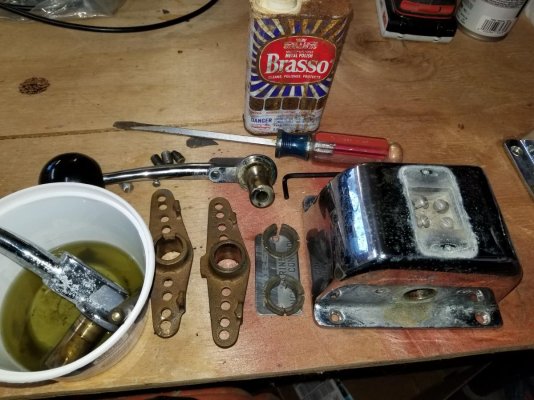
It was a little cruddy inside (gummed up lubricant) and a little crusty on the outside (light corrosion.) I initially thought Brasso would do it, but the corrosion was a little more than it could handle. I switched to a 3" buffing wheel on my little 90 deg air grinder and some white rouge. It shinned up okay. Here it is still disassembled:

20180918_192048.jpg

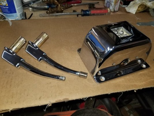
And put back together:

20180918_194657.jpg

We'll make sure to take good care of the surface; I wasn't able to get all of the pitting out of the surface - there's still a little there, and it started to look like I was wearing through the chrome near one of the large bore holes for the shafts. We'll monitor it, but eventually it will probably be a rechrome. I'm sure I'll come up with a thing or two to go along with it!

Also got the lower helm shifter disassembled. Close inspection shows the shift detent plates are worn - both have a rough groove in them. They aren't reversible, it looks like there is a light stamp on the back at the top of the curve to get them to match the shape of the shifter.

20180918_195031.jpg

With the manual I found, I had the part number for the shift detent kits, and they are still available. (It looks like SeaStar still sells the same control. I'd half expected it to be obsolete.) I have two detent kits on the way that will be here this weekend. Tomorrow I'll get the lower helm shifter put back together and next time we're at the boat I hope to see that we've taken enough friction out of the system that the FB shifter will work like it should.


David
 
A lot of the time when a shifter or throttle is stiff it is due to the cable. Sometimes you can lube the cable and sometimes they need to be replaced.
 
in your first pic, shouldn't the water be injected in the top of of the upper elbow? it looks like there is is a tap for it there. a pic of the side of that would be helpful. i.e. rotated 90 degrees.


jim

That very well could be. If I were looking at this setup knowing what I know now, I would think it should go there. Better yet there should be an injection port on the downhill side of that upper elbow, but there isn't one there.

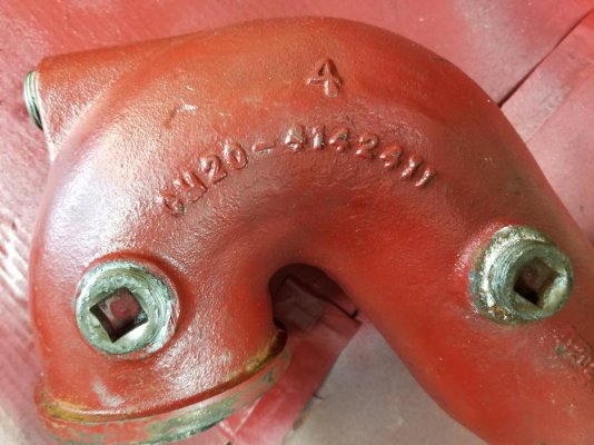
Here's a pic of the one we have taken off. The lower left portion of the photo shows the portion of this upper elbow that connected to the lower elbow on the exhaust manifold. (The portion in this photo off to the right is where the exhaust hose attached.)

There are three ports, one on the top and two on the side. I'm assuming they are injection ports, but I'm not sure about the two on the side, they must be somehow connected to the water passages. With the scaling and corrosion in these particular pieces they aren't going back on, and I'm still not keen on trying to replace them and make them work. The simple fact an adapter (that I have yet to find a replacement available) is needed to switch from Ford to Chrysler is a red flag for me...I can find the swivel and lower elbow from a number of sources, total cost is about $350 or so per engine. But the swivel goes together with an o-ring seal, and I don't know that I want to experiment with trying a new set with the raw water plumbed to the upper injection point, and that o-ring joint not getting cooled...

20180914_174609.jpg
 
Now I'm second guessing myself. I started looking through engine room photos of all the boats we've looked at (or looked online at) and found this, which looks like my same setup but using that top injection port. This is on a 40 ft PT Trawler for sale in La Conner.

Has anyone else ever seen these swivel exhaust elbows on FL engines?

6557918_20180112134304123_1_XLARGE.jpg
 
Now I'm second guessing myself. I started looking through engine room photos of all the boats we've looked at (or looked online at) and found this, which looks like my same setup but using that top injection port. This is on a 40 ft PT Trawler for sale in La Conner.

Has anyone else ever seen these swivel exhaust elbows on FL engines?

View attachment 81033

Self answered. Had a really good conversation with Brian at American Diesel this week. He is familiar with those swivel exhausts being used on Lehmans. As I thought, they can't be used without water into the lower section. In addition to possibility of leaks back toward the manifold the sheer weight of them hanging of the exhaust manifold causes long term issues.

Tomorrow is a work day on the boat, we'll be pulling all the rest of the engine room exhaust apart, finishing my waterline measuring as well as looking at how to get the most height in the engine room for the exhaust and getting a start on some additional work detailed later in the post.

Also had a great conversation with AD about the current status of our engines and replacement parts to consider and spares. Brian emailed us a parts/price list. I just have to double double check the raw water pumps so I don't order a wrong part. I know one of them is a Johnson pump, but need to make sure they both are, and double check the model since there is a possibility of either a 3/4 or 1" pump on the boat. Once that's for certain I'll start ordering parts next week - coolant overflow kits, hose and belts, RW pump kits, pencil zincs, rocker cover gaskets (at least one is seepy with snug fasteners.) We'll use hose replacement as an inspection time for the heat exhanger/oil coolers. I need to inspect the oil hoses and double check some receipts. Our PO bought some oil hoses from AD, and they may be newish.

Some other side projects during this fall in the engine room include, in order of priority:

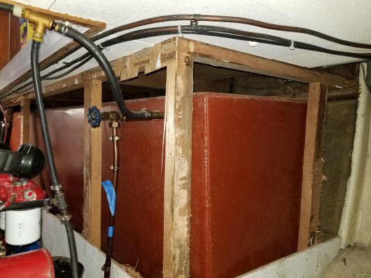
Clean and Inspect Fuel Tanks: We've removed the sound insulation from around the tanks for inspection and possible tank cleaning. They look good on the outside.
-We'll be installing a fuel transfer filter/pump system (that will also give us ability for polish if needed) that will also me to pump out one tank (both are currently way below 1/2) for interior inspection/cleaning. Its design is being stolen from this forum (TomB and others.) The tanks have never been opened.
-Since we're digging into the fuel system, we'll also be replacing the current single Racors with dual setups. I'll post more about that project tomorrow. --
-We have a great vendor lined up if the interior fuel tank work ends up being more than we can handle (PetroClean out of Bellingham.) They were nice enough to spend time on the phone with me this week discussing the project, provide recommendations for DIY, and provide services they could provide depending on what we find.

Replacing the domestic hot water tank: It is at end of life, seeping water and not really heating efficiently, plus it needs to move to do the fuel tank project. I spent some time reading on the forum the last couple days about what to replace it with. Not certain yet, but leaning toward the Iso-Temp / Iso-Therm lines. Need to do some more research about the implications of gallons-vs-wattage-vs-needs and how all this affects genset runtime at anchor. Key driver - Y-von wants hot showers to start her day (and wants me to shower sometimes, too.)

Installation of an Aqualarm system: Dual station dual engine engine 5 alarms, Oil Press, Water Flow, Eng Temp, 2 bilge alarms, 2 fire alarms (heat, rate of rise.) While ensuring our gauges work (they need it as they do not agree and are suspect) and are looked at (I'm obsessive, but not all crew are) I want to make sure we have quick and firm warning of major issues.

12 VDC wiring cleanup:
-Removal of un-fused positive bus on aft eng room bulkhead and re-wire to fused terminal block in forward electrical compartment.
-We have discovered 4/0 battery cable (and other undiagnosed wiring) from both house and start batts that go from battery banks to the inverter/charger are laying along the outside of a stringer in a place they could sit in water - they need to be supported and out of a possible watery space (they are almost underneath the stbd RW strainer.)

Battery bank cleanup:
-We are also going to move the Genset battery out of its current location underneath the genset. A RW leak during our first days on the boat showered it in saltwater.
- We are going to see if we can move the start battery (large Northstar 210 AGM) out of its current location under the false floor in the center bilge to sit either against the aft eng room bulkhead or possibly on the port side of the port engine.
-Add spacers under the house battery boxes to move them up off the center bilge area so they are at or above the center stringer height to lessen the chance of severe flooding shorting them out.
-All these changes will put both the start and Genset batteries into better locations with little to no increase in cable length. The cables from the batter to the stbd engine starter will be approx 3-4 feet longer if the batter moves outboard of the port engine. It will also make room to increase our house bank from 4 GC-2 6 volts to 8, which will be a nice sized bank for longer life.

Eng Room cleanup / Paint:
-No sense touching all this and not cleaning and refreshing it all.

DISCLAIMER: I have a diseased mind and have missioncreepitis. Don't listen to my ramblings. I want to have the ER done by December and can't possibly finish it all. :D

More pics to come after the weekend!
 
Last edited:
Add a pair of fuel pump mounting gaskets (I would buy a spare pump, they are cheap) and check that the injector seals, the ones that seal to the block, are in good shape; when you change the oil, add the measured amount, do not use the dipstick. Change the oil in the Simms pump the same way. Oh, make sure you understand the process of "burping" the coolant jacket. Aligning the engines must be done in the water.

Plan to service all 12 injectors, find a farm equipment place to do it - cheaper.
 
This from 29 years of caring for a pair of FL 120s.

Regarding the valve cover leaks, over the years somebody has doubtless over tightened the screws beyond the 22-INCH pounds specified and bent the gasketed surface. Take a steel ruler to the underside to find out how much indentation there is. Take the covers to your anvil and with hammer tap the surface back straight. With new gaskets, you will have no leaks if you do this. Otherwise - leaks.

While you are at it, re-torque the head bolts (done with a warm engine) and check the valve clearances (also warm). Now remove and overhaul the injectors as suggested before - do it every 2000 hours. Don't forget to check the injector pump timing too. That's a fun one requiring a mirror to the the timing marks from the bottom of the engine.

Injector pumps need oil changed every fifty hours. Attach a tiny spigot to the drain hole for ease of oil draining.

Do yourself a favor and change all the engine cooling hoses to silicone.

I bought my trawler and immediately changed the incorrect upward pointing exhausts to Verna lifts, but it was too late for the port engine. After 80 hours, it began a noisy clanking due to a damaged number 6 cylinder from seawater trickling back in after shutdown. Hope yours does not do that to you. BTW, you will need to replace those exhaust elbows about every five years; so put some anti-seize on the four bolts.

Flush the engine cooling systems, coolant side as well as the seawater side. If you don't pull the coolers for testing (which I recommend), flush with Barnacle Barrier. If one of your engines heat potable water, add shutoff valves on the engine in case there is a casualty with the water heater or hoses.

As a preventive measure, I would replace the fuel lift pump because if the diaphragm goes, guess where the fuel goes? Yep, into the sump oil.

Install a fuel polishing system as well as a small Facet pump as a priming pump (or make the polisher pump dual function). With Racor filters (or whatever primary filter you have) often being higher than the bottoms of the fuel tanks, you can find yourself in trouble if you open a filter top to change the element and the suction is lost to the tank. Either you carry some fuel in a container to pour in there or get a priming pump. Added benefit - priming pump can keep an engine running if there is an air ingestion problem. All you have to do if the engine dies from air ingestion is turn on the pump, make appropriate valve changes to provide pressure to the fuel supply for it and crack that 1/2" bolt on the side of the Simms pump to watch all the bubbles come out followed by solid stream of fuel.

I have one port of one Simms pump leaking and had to purchase the special tool to tighten it. It was basically a socket with thirty or some teeth to attached to that outlet port. Solved the problem. You need a tubing wrench to remove the steel injector line first.

Spares I carried for this engine:

one complete seawater cooling system including Johnson pump, hoses, and coolers

one coolant circulating pump

set of copper crushing washers for reinstallation of the injectors (yes, but a new set when you have them overhauled as suggested above)

one spare injector for trouble shooting (never used)

one set steel injector lines (never needed one, but....)

vee-belt

seawater impellers

spare radiator cap (they do go bad)

valve cover gasket

spare coolant temp sender

spare coolant temp alarm sender

spare alternator

probably more crap I collected over the years
 
A lot of the time when a shifter or throttle is stiff it is due to the cable. Sometimes you can lube the cable and sometimes they need to be replaced.

That was our thought. We took the shifters off to see what condition the cables were in; being able to move them by hand was a good sign, but I don't know what level of manual resistance would give a shifter problems. We also checked the transmissions themselves, and again could shift them easily by hand but don't know what level of resistance is acceptable. I do need to look at the transmission manual and see if there is a resistance measure to look for.

We were out at the boat putting this all together today and noticed when we were putting everything back together the brass connectors that hook the cables to the shifter arms are all badly worn; some are even out of round. We put them together anyway and things are still stiff, but looking closely we can see the worn shafts on the brass connectors (called a cable pivot on the drawings) binding as we move the controls.

20180929_212646.jpg

Going to order all new for both shifters and we'll see how that progresses. Once we have fixed all the faults we've found with the shifters we will have to look at cables as cause.
 
Rgano:

Thanks for this information. Most everything you said exactly echoes my conversations with American Diesel.

Regarding the valve cover leaks, over the years somebody has doubtless over tightened the screws beyond the 22-INCH pounds specified and bent the gasketed surface.

Brian's words almost exact.

Take a steel ruler to the underside to find out how much indentation there is. Take the covers to your anvil and with hammer tap the surface back straight.

While you are at it, re-torque the head bolts (done with a warm engine) and check the valve clearances (also warm).


Exactly what we'll be doing on all counts. Additionally, we are in a big farming area so I will be looking into that source for the injectors.

Attach a tiny spigot to the drain hole for ease of oil draining.

I was thinking of doing something like this, I'll have to search around for ideas on how this might look. My PO installed oil change hoses on both engines, but not the transmissions or anything special on the injector pump.

Do yourself a favor and change all the engine cooling hoses to silicone.

I haven't seen or heard of doing this for FL. We used to have those installed in our patrol cards back in the days of V8's. (maybe they still put them on the v-6s we have, but I haven't noticed them if they are, the old ones were blue.) I have already got whatever American diesel supplies which is can't imagine is silicone. I know the advantages in terms of handling more heat when running hard - that is why we always used to get them. Is that the reason for wanting them or is a life issue?

I bought my trawler and immediately changed the incorrect upward pointing exhausts ... BTW, you will need to replace those exhaust elbows about every five years; so put some anti-seize on the four bolts.

Yes. When I spoke with Brian at AD he related the same issues with water getting down into #6. I had also asked about the high uncooled exhaust with a downhill water injection some people are running. He discouraged this because the high heat in parts of that setup can boil cooling water. I am dealing with a stuck bolt right now removing the second elbow! I am a big believer in anti seize.

If one of your engines heat potable water, add shutoff valves on the engine in case there is a casualty with the water heater or hoses.

Thats a good idea - consider it done! We are in the process of replacing a water heater anyway, along with hoses so its the perfect time.
 
Fuel Tank Cleaning sub project

Big day today.

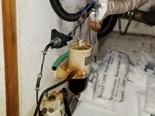
Trying to figure out fuel transfer/polishing has turned into looking closely at the mess of fuel lines, the Racors, black water plumbing, and some really bad 12VDC wiring (unfused terminal blocks feeding the Surewire heater controller and aft head components with a partially melted wire) mounted to the aft engine room bulkhead. We haven't traced where the supply for this comes from, but we're pretty sure its running through the 75 amp breaker you can see. It does appear that the loads running off that bus have been (at least at one point) to much hence the melted insulation. Scary!

20180909_145515 crop.jpg

Additionally, the Racors are mounted way outboard and would be dangerous to work on underway. (you have to lean over the moving shaft to access them. No good!) It has basically caused us to decide we are going to remove and refit most of those components mounted on that after bulkhead.

20180905_185831.jpg

The plan will basically be to remove the unfused bus and install a fuse block. i still have to trace the origin of the feed coming to the unfused bus, and make sure THAT is fused as well. We are seriously considering abandoning this whole idea and bringing all the loads from a single point in where all the AC and DC distribution is in the electrical panel in behind the lower helm. We need more capacity there as all current breakers are in use. I'm going to have to research having a fuse block instead of individual breakers for each load.

After we deal with the bogus wiring, we'll be moving components out of the space around where the buses were and put both Racors there. We'll redo the fuel plumbing to allow either Racor to draw from either or both tanks and feed either or both engines. That will give us decent redundancy to tank a filter offline if we have an issue. I'm still trying to decide on the fuel polishing issue. I have decided to use the transfer pump I bought for this project as a permanent install oil change pump for the engines.

On to TODAY's work! We used a Marco UP3 reversible oil transfer pump, along with needed hoses and fittings to transfer all the fuel from the stbd tank to the port tank. We used the crossover line (for the tanks to equalize their level) but won't be doing that again. The crossover is not filtered in any way.

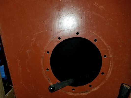
I marked, drilled bolt holes and cut the center hole for a Seabuilt 10" access port. Sorry, I missed taking a photo of the finished center hole!

20180929_161835.jpg

The tank is about 107" overall, and the first bulkhead is about 30" from the aft end. Looks like they used whatever scraps they had to help tie the bulkhead to the tank sides!

20180929_171537 crop.jpg

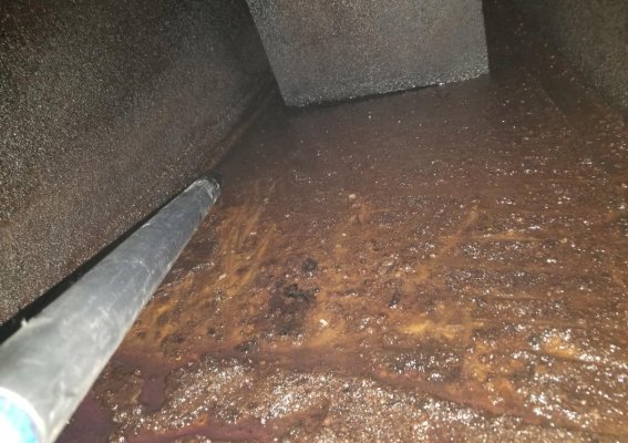
Inside I found - MUCK. It was an inch or more deep nearest the supply, reducing to a scant quarter inch 18 inches away. It appears most of the actual debris is in the lowest portion of the aft bulkheaded space of the tank.

20180929_174036 crop.jpg

I had expected to find corrosion inside. I noted there is corrosion low, sides, and high in the interior. It seems consistent on the bottom where there was the most muck, which is what I was told to expect.

Altogether a first vacuum of the muck resulted in two full 8 oz butter cups of crud. I haven't done anything yet but vacuum with a round extension pipe!

20180929_194309.jpg

Next time out I'll be doing more cleaning, going to stick with only putting plastic inside the tank. I don't know that accidentally rubbing copper or brass will make the corrosion that much worse than it is but why take chances?

Also going to put a camera up past the baffle and have a look at whats up there. If in fact all gunk has settled out into the aft end we may not opt to put ports in the other two sections.

Progress! After we get this cleaning done we'll be putting on new valves (crossover, supply, and two for the sight gauge.) Then new fuel lines run to the new Racor locations, and finally we can put new engine exhaust in and then move on to the port side. Only 25 steps and we're done!

BTW, in addition to helping hand me things while I was wedged over the transmission and into the starboard hull behind the tank, Josh went through all the seacocks for the aft head, galley sink, fwd head, and the raw water water down. He found a bad hose (incorrect!) on the main forward bilge pump - clear vinyl hose from a tee to the seacock that was old and cracked. We'll have to replace with bilge hose then those seacocks will be done.

David
 
The copper washers for the injectors can be annealed with a propane torch and reused. For a spigot for draining your Simms pumps you will need to machine a thread adapter for an icemaker valve. Switch the inside Morse control for the outside one to get more life out of the chrome...

When you pull the injectors for checking, take a good look inside number 6 cylinder to check for damage. Might as well find out now while you are still on the hard.

Break a leg!
 
From post #13 (madoc) and your answer at #16, it would seem the two elbows, one that has the raw water connection and the one on top of it that is the subject of the posts I have noted, appear the same on the outside. I doubt they are the same on the inside, as a "Water injection elbow" should be a sleeve,surrounded by a water passage that opens to the inside at the end of the elbow furthest from the engine. Those are significantly more complex (read "expensive") to make that a simple cast elbow. That moves the internal injection point from where the hose attaches to the far end of the elbow, which, if mounted with the water connection on it top side, down slope so there is no possibility of any of the water dribbling back into the manifold, or cylinder #6. You should be able to tell once they are all disconnected, and then get the correct bits when it is time to go back together.
Good luck with it and keep the pictures coming.
 
Fuel Tank Cleaning sub project con't

Pretty good day today, or not.

Here's a photo I missed from yesterday of the inspection port cut out. Still have to go in and file/trim the holes. Should have done that before all the cleaning...

20180930_131818.jpg

I made good progress cleaning the area of the tank I started on yesterday. (the aft 1/3 of the starboard tank. What looked horrible cleaned up pretty well on first look. Most of the corrosion spots were just surface stuff. My biggest problem of the day had seemed to be the awkward position I have to be in to work here (thigh high on stbd transmission, shoulder low on sbtd lower hull) and the fact my bucket head vacuum does not like the thick gunk from the bottom of the tank. We used reclaimed diesel vacuumed out yesterday with the reversible pump to spray down the area I was scraping with a plastic fish tank algae scraper and a couple homemade acrylic scrapers.

20180930_131754.jpg

And I couldn't resist doing a "from in the tank looking out" selfie. :eek:

20180930_135054 smaller.jpg

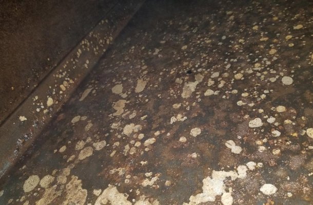
Here is a view of the mostly cleaned area. As you can see, most of the corrosion is in an arm's reach area of the lowest/aftmost/inboardmost section of the tank - where all the gunk was. And most of it cleaned up well and appears to have just been on the surface.

20180930_150009 crop.jpg

Closer inspection looks to have at least several fairly deep pits in the center of the worst of the corrosion. I'll have to measure them, but I'm guessing they are almost half the 1/8" wall thickness.

While I know it is controversial, we may be going the route of aircraft fuel sealant at least in this bottom end of the tank. It hasn't rotted through in 38 years, and I'd like to keep it that way for another 38. A fuel tank replacement is not in the cards right now. Its the gamble we took buying a TT 38 years old with hidden tanks, and why the first thing we've done is open things up so we know. The rest of the tank is in great shape. Our boat was made with fiberglass decks, and the fuel fills are in raised sections so its not possible for much water to leak down the fill tube if it were to leak, and don't see signs of water drips/corrosion on the outside of the tank, 80-85% of which I have been able to see. (both sides, most of the bottom, all of the top, only the fwd end can we not see.)

20180922_175313.jpg

A little set back, but I think we have a plan and we will have a solid fuel system when we're done.

More on the fuel system. I haven't had a chance to draw it out digitally, but basically I traced everything today. I

Its fairly simple, each tank is connected both with a lowest-drain-point cross connect and a high fuel return. The fuel returns for both engines and the genset all all connected together at the engine room ceiling and are interconnected to both tanks.

For supply, the Webasto heater is plumbed off the port tank cross-connect. It has its own smaller Racor.

The port engine feed goes through a Racor 500, then to the engine. The starboard engine feed goes through another Racor 500, then to the engine. Both feeds are connected to each other with a shut off valve in between. The genset feeds off the starboard engine side of the shut off valve. In case of a fuel problem, I could shut off one tank and feed both engines with the other, but not completely isolate a filter under way.

Oh, and the starboard side Racor 500 is plumbed backwards. :ermm: I keep thinking, why didn't my surveyor see all this stuff, but I realize that I've spent a dozen hours fretting about the fuel system alone and just realized it...And he DID find plenty.

All this has firmed up our plans to clean up the aft engine room bulk head and reconfigure the two racors with lines/valves that will let us run each side seperately, or both engines off either filter and either tank. This week Josh is going to pull the racors and bring them home. We'll build a filter/valve manifold mounted to something here at home that we can take out and install quickly on a weekend.
 
I haven't posted updates in quite a while, but that's because between work and school (13 credits, two A's and two B+'s for fall quarter!:socool:) and the boat, I've had very little time to document all this work and do it justice.

Josh (my 18 year old son) and I have been working on the boat every weekend, usually 10-16 hrs each weekend. I think we took off two weekends in December for family events. Additionally, he's been stopping by during the week on some days either before or after school (he's going to a marine tech school in Anacortes.) I'm finally getting to the point that I have some progress and completion going on, and thought I'd get some of what we've done up here.

My last post was progress on our work on the starboard fuel tank. I had opened it up, found the gunk all settled in the aft (lower) end of the tank, cleaned that gunk, and found corrosion with pitting underneath. There is no sign either tank has ever leaked except from a seeping valve on the port tank, so anything here is prevention.

Fuel Tank Cleaning - Sealing the pitted area

I researched possible solutions, and decided on the Flamemaster product line produced by Chem Seal. The product is CS-3204, which is a I decided to go with a thixotropic mix instead of a self leveling liquid. I was worried the self leveling liquid would pool in one area and not evenly coat everything, since the tank IS sloped. What I bought was CS-3204 class B2. The B is the thick version that is guaranteed not to run or sag and can be applied to overhead surfaces, and the 2 means there is a 2 hour working time.

This product is made for the aerospace industry, and is likely the like/same product you have heard of tank cleaning companies using to do similar repair or preventative maintenance. From their product literature:

"....a fuel resistant sealant for use on integral fuel tanks and
pressurized cabins as well as other areas subject to contact with
aircraft fuels, lubricants, oils, water and/or weathering."


Their literature also specifies that they don't warranty it for other fluids or fuels. Using it for a marine diesel tank instead of a jet fuel tank is a risk I decided to take. Jet A is primarily really clean kerosene, diesel is a dirtier oilier version of kerosene. My tanks don't leak, but have pitting and one day will. Perhaps this sealant will keep them from leaking as soon.

After gearing up with a chemical respirator rated for it, I commenced to cleaning the tank. I didn't attempt to grind or sand, I did scrape all the corrosion down, and cleaned all the metal "dry", ie no trace of diesel oil on the areas I sealed. This tank cleaning project only involved the loose gunk settled in the bottom end of the tank. The entire tank still has a think layer of a greasy consistency on it; the danger to the filters or the tank itself from that is minimal, so we didn't invest the time or money to put more access ports to do a full "steam cleaning." I did use mineral spirits then acetone to clean the metal oil free.

Working with the sealant was a joy. I used the chemical respirator for that, too. It was pretty thick in consistency, and absolutely sticky. Once on something, it does not come off, period. The product literature talks about cleaning it off with methylene chloride!

Here's a pic of that bottom end of the tank with the sealant on it. It was nasty stuff to work with.

Stbd Fuel Tank - Sealant down over corrosion.jpg

I applied this to the tank in October, and the temps outside were low. The product requires a 72 hr cure time at 77 deg F, and I intended to pump all the fuel from the port tank into it, so I needed to make sure to cure it. We ended up using a oil filled space heater and got it over 70 for a week (5 days.)

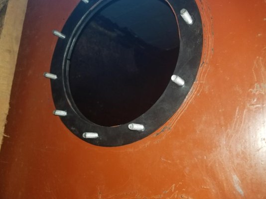
Once it was cured, I installed the access port. Here's a few shots of how those go in. This is the 10' access port from Seabuilt here in Washington. Forgive that they're upside down. I've tried resizing, rotating/saving/rotating, etc. For some reason the photoshop on this computer isn't working, I'll make sure I get these better in the future.

Stbd Fuel Tank - inspection port installation.jpg

Stbd Fuel Tank - Inspection port installation 2.jpg

Stbd Fuel Tank - Inspection port installation 3.jpg

Also, here are a few shots of the tank exterior. No signs of previous water on the tops of the tanks - in fact they are all dusty. Even the fill port has only some surface rust on it.

Stbd Fuel Tank - no past water leaks on top or at fill.jpg

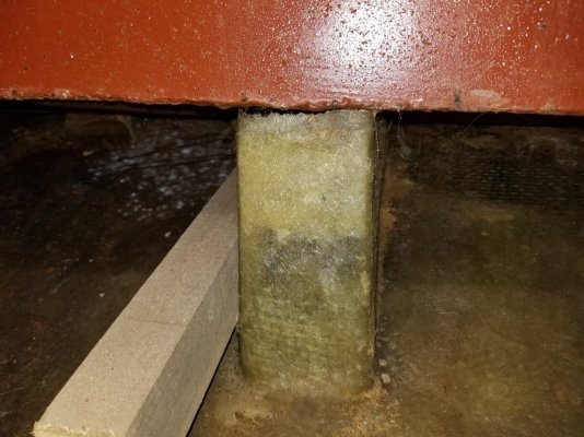
Here is how these tanks are mounted. They have some manufactured fiberglassed in wedges the tank sits on, aside from these the bottom is exposed to air - no chance of it sitting on moisture.

Stbd Fuel Tank - Mount example.jpg

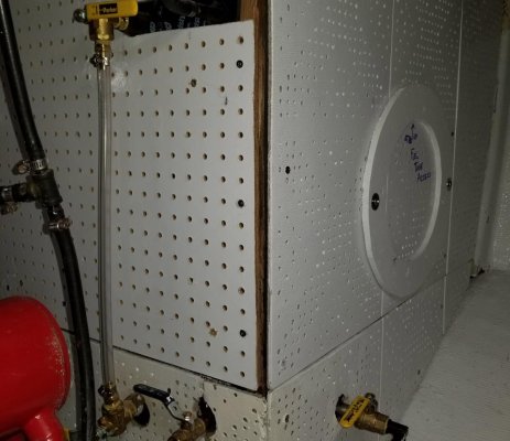
Next was to put it all back together. When we took the bulkheads (tank surrounds) off, there was a section on each tank wall where the original plywood/sound tiles had been removed and replaced with pegboard. We found that both tank "spaces" connect directly with the salon in some way, so we decided to add some sound proofing.

I didn't research or attempt to find the matching sound tiles. I just took the pegboard and glued it down to some 1/4" marine plywood. I bought two rolls of 48" x 15' of 2 lb mass loaded vinyl, which is a sound proofing material used in construction. It was perfect in this case - it's only 1/4" thick, and I could easily cut it to fit all of the fuel talk bulkheads. We installed the MLV first with staples, then fastened all the panels back into place with stainless screws ever 6-8 inches.

Stbd Fuel Tank - Bulkhead going up with MLV.jpg

Fuel Tank - Mass Loaded Vinyl seams sealed with vinyl tape.jpg

On the end panel, I made an access port in the panel so I can easily access the port in the tank.

Stbd Fuel Tank - Bulkhead up with access added.jpg

I won't repeat it all, but everything same same on the port side tank.
 
I haven't posted updates in quite a while, but that's because between work and school (13 credits, two A's and two B+'s for fall quarter!:socool:) and the boat, I've had very little time to document all this work and do it justice.
Josh (my 18 year old son) and I have been working on the boat every weekend, usually 10-16 hrs each weekend. I think we took off two weekends in December for family events. Additionally, he's been stopping by during the week on some days either before or after school (he's going to a marine tech school in Anacortes.) I'm finally getting to the point that I have some progress and completion going on, and thought I'd get some of what we've done up here.

My last post was progress on our work on the starboard fuel tank. I had opened it up, found the gunk all settled in the aft (lower) end of the tank, cleaned that gunk, and found corrosion with pitting underneath. There is no sign either tank has ever leaked except from a seeping valve on the port tank, so anything here is prevention.

Fuel Tank Cleaning - Sealing the pitted area

I researched possible solutions, and decided on the Flamemaster product line produced by Chem Seal. The product is CS-3204, which is a I decided to go with a thixotropic mix instead of a self leveling liquid. I was worried the self leveling liquid would pool in one area and not evenly coat everything, since the tank IS sloped. What I bought was CS-3204 class B2. The B is the thick version that is guaranteed not to run or sag and can be applied to overhead surfaces, and the 2 means there is a 2 hour working time.

This product is made for the aerospace industry, and is likely the like/same product you have heard of tank cleaning companies using to do similar repair or preventative maintenance. From their product literature:

"....a fuel resistant sealant for use on integral fuel tanks and
pressurized cabins as well as other areas subject to contact with
aircraft fuels, lubricants, oils, water and/or weathering."


Their literature also specifies that they don't warranty it for other fluids or fuels. Using it for a marine diesel tank instead of a jet fuel tank is a risk I decided to take. Jet A is primarily really clean kerosene, diesel is a dirtier oilier version of kerosene. My tanks don't leak, but have pitting and one day will. Perhaps this sealant will keep them from leaking as soon.

After gearing up with a chemical respirator rated for it, I commenced to cleaning the tank. I didn't attempt to grind or sand, I did scrape all the corrosion down, and cleaned all the metal "dry", ie no trace of diesel oil on the areas I sealed. This tank cleaning project only involved the loose gunk settled in the bottom end of the tank. The entire tank still has a think layer of a greasy consistency on it; the danger to the filters or the tank itself from that is minimal, so we didn't invest the time or money to put more access ports to do a full "steam cleaning." I did use mineral spirits then acetone to clean the metal oil free.

Working with the sealant was a joy. I used the chemical respirator for that, too. It was pretty thick in consistency, and absolutely sticky. Once on something, it does not come off, period. The product literature talks about cleaning it off with methylene chloride!

Here's a pic of that bottom end of the tank with the sealant on it. It was nasty stuff to work with.

View attachment 84473

I applied this to the tank in October, and the temps outside were low. The product requires a 72 hr cure time at 77 deg F, and I intended to pump all the fuel from the port tank into it, so I needed to make sure to cure it. We ended up using a oil filled space heater and got it over 70 for a week (5 days.)

Once it was cured, I installed the access port. Here's a few shots of how those go in. This is the 10' access port from Seabuilt here in Washington. Forgive that they're upside down. I've tried resizing, rotating/saving/rotating, etc. For some reason the photoshop on this computer isn't working, I'll make sure I get these better in the future.

View attachment 84488

View attachment 84489

View attachment 84490

Also, here are a few shots of the tank exterior. No signs of previous water on the tops of the tanks - in fact they are all dusty. Even the fill port has only some surface rust on it.

View attachment 84478

Here is how these tanks are mounted. They have some manufactured fiberglassed in wedges the tank sits on, aside from these the bottom is exposed to air - no chance of it sitting on moisture.

View attachment 84477

Next was to put it all back together. When we took the bulkheads (tank surrounds) off, there was a section on each tank wall where the original plywood/sound tiles had been removed and replaced with pegboard. We found that both tank "spaces" connect directly with the salon in some way, so we decided to add some sound proofing.

I didn't research or attempt to find the matching sound tiles. I just took the pegboard and glued it down to some 1/4" marine plywood. I bought two rolls of 48" x 15' of 2 lb mass loaded vinyl, which is a sound proofing material used in construction. It was perfect in this case - it's only 1/4" thick, and I could easily cut it to fit all of the fuel talk bulkheads. We installed the MLV first with staples, then fastened all the panels back into place with stainless screws ever 6-8 inches.

View attachment 84487

View attachment 84480

On the end panel, I made an access port in the panel so I can easily access the port in the tank.

View attachment 84481

I won't repeat it all, but everything same same on the port side tank.

=====
fractalphreak,

You choice of the Chem Seal CS-3204 is a good one. The competition is PPG (Pro-Seal) P/S 890, PR-1440 also an excellent product. I've used both in repairing aircraft fuel tanks which are rubber, not metal. But suspect you'd have good luck with your boat tanks.
 
Rest of the Fuel System

Great week for us. We finally got the call that a spot was available in Shelter Bay in LaConner! We'll be moving the boat from dry land storage in Anacortes to the wet slip in the 2nd or 3rd week of February. I must admit I'm also a little stoked to learn that marina tenants get use of the pool there too! :D

More good progress on the boat. We've replaced any substandard below the waterline hoses and clamps, removed and capped off three unnecessary through hulls, and relocated one unneeded seacock to one of the engines - all three engine seacocks are Groco BV-750's. We noticed all three were hidden under the false floor in the engine room. Since none of them are in places we will step or kneel on, we cut access holes in the false floor big enough that we can see and operate all three.

Over the last two weekends, Josh and I got the filter assembly mounted - its on the center of the aft engine room bulkhead and fuel lines run from the tanks. Between its width and a small amount of space we had to leave for some electrical wiring, the small Racor (for the genset and heater) is a little farther a reach than I'd hoped, but still MUCH better than all the way across the transmission/driveshaft/outboard stringer down low less than a foot off the hull. (Here's of photo of the port side Racor - dedicated to the port engine only- and the small Racor)

20180905_185723 crop.jpg


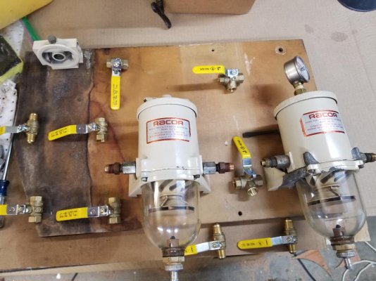
All together and bled through with no leaks. I'm pretty happy with how it came out. It looks like spaghetti, I'm still working on making labels for it, but its very functional and easy to access the filters for maintenance. Note all three filters are spaced off the board, so I have room to hang a small bucket under them to keep from spilling anything as I work.

20190127_165144.jpg

Basically, fuel comes in at the two valves at the lower right. Port or starboard tanks or both. I did not plumb a valve set for the return lines - they are plumbed with hose from the engines up to the ceiling, then a common line out to the top of both tanks. I'm adding valves to those returns on the tanks, and will have to switch those as I switch the tank valves. Above the two inlet valves there is a tee, one side goes to the larger Racors and one side goes to the smaller one. The lower L valve switches the Racor inlet from one side to the other. The upper L valve must be set to match, it switches the outlet of the Racor. After the Racors there is a tee off to the vacuum gauge. (The PO had the vacuum gauge/brass adapter in place of the tee handle on the right. Sunday Josh found the old tee handle in a box of spare parts, so we'll reinstall that Saturday.)

The fuel then splits off into two lines, one for the port engine and one for the stbd. We bought new A1 fuel line to run to the lift pumps on both engines, and since we moved the Racors we just did new copper lines from the tanks to the new fuel filter board.

The fuel line to the smaller Racor does the same thing, it goes through the filter then splits off into two lines, one for the genset and the other for the Webasto heater. I didn't put a vacuum gauge on this one, I figure if I start having fuel starvation on those two units its less critical than on the engines.

Here's a few shots of the filter assembly during its build:

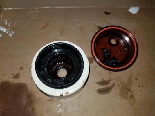
All three filters were full of the same black crud from the tanks. Good move to preemptively clean them out.

20181112_120546.jpg

Here's a Racor disassembled for cleaning. All three were rebuilt with all new seals throughout. I'll probably regret not stripping and painting the one with the missing paint every time I look at it.

20181112_182402 land.jpg

Here is me figuring out a layout that could fit in the space I had:

20181115_191958.jpg

And a final assembly before painting the lines:

20181206_195049.jpg

It would have been easier to buy a dual filter Racor set up, but lots of dollars more. They are also not the preferred marine versions with the heat shields. But this gives me all the functionality of one, plus I used a lot of pieces I already had, and got to play copper bender for a while. I painted all the lines on the filter board with yellow enamel mixed with hardener. Since this photo was taken, Josh headed out early one day this week for school, cut and fit the new fuel line for the other engine, connected it and bled it. We'll finish the genset and heater Saturday, and can call our fuel system major cleaning, PM, relocation & refit complete for now. Our only remaining task will be 10 or 20 gallon at a time filling and marking our new sight gauges.

We're getting close on the exhaust - we have all the Centek 90s and hose, but ended up needing another 28 clamps to fit 3.5" hose. They won't be arriving until Tuesday, so we won't be finishing the exhaust 100% until the following weekend.

More major projects remain. Those include:
  • Waste System
    We found that one or more of the fittings from the built in waste tank (even with the aft engine room bulkhead, integral between the stringers) has failed, leaked moisture into its own plywood core, and rotted and started to leak. I cut out rot until I confirmed it hasn't gotten into the engine room bulkhead wall itself (whew, that's a major structural support of the boat) but does mean grinding off the whole front of the tank to repair. To do that I'll have to pull out the start battery and box. Since I want to relocate those anyway, I'm putting off that project for a month or two, and putting the aft head out of service. In the meantime, we're building a custom vinylester holding tank fit to the hull contour up in the front port corner of the engine room, and it will be dedicated to the forward head. That will serve us for day or weekend trips and give me time to do other battery bank upgrades/relocates at my leisure. Also, once both holding tanks are up and running, I'll have an approximate 40 gallon aft tank and a 27 gallon fwd tank, which is decent total capacity.
  • Fresh Water System
    Still have to mount the pressure pump in its new location, and create/connect the water heater, boat water lines, pressure tank, and engine heat exchanger lines. We have all the materials, but a good chunk of a day's work to do it all right.
  • Electrical System Fixes and Improvements
    We found the echo charger for the genset battery has failed. That battery is getting relocated out from under the genset in the next week or two and to a place closer to connect the echo charger. I need to build a battery box for it first, its currently sitting in a cheap plastic thing with no lid. We also have one more unfused positive bus we found in the lower helm electrical bay. Its fed by an unfused large cable and has more than a half dozen wires coming off of it to who knows what. We need to add a circuit breaker to that cable, and replace the bus bar with a fuse panel we have purchased, trace all those wires and label them...
  • Electronics Upgrades
    Install stereo system - we have a new Fusion stereo, the model that allows you to control zones. We'll have the cabin as one zone, and the flybridge as another. Its a cool system that you can control with a smartphone or tablet. We also have a low power (400W) amp and some nice speakers for it. I like tunes! Of course, I don't like the current location of the stereo - forward and to port on the dash. you have to lean awkwardly over the dinette to turn it on and off or change channels. So the project will involve new power wiring and some rerouting of the speaker wires.
    And lastly, we have an AIS transceiver, AIS VHF antenna, AIS GPS antenna, a Nemo from Rose Point and some NMEA2K network components to install. I like to use CE, and am going to take a stab at running the ComNav from it, as well as see if I can import the MARPA sentences from the radar. Those will be last, after we have everything else up to snuff and before I spend the summer out on the hook varnishing brightwork. :blush:
 
A couple of other little completions

I almost forgot - I'd tried to post these a week ago and couldn't get them to post right, my photo editor has gone permenantly blue circle and they needed cropped...:banghead:

Here's a pic of the new coolant recovery system on the stbd engine. I built the bracket so we could put it in a place that is super easy to access, but out of the way of most every maintenance need on the engine. (To prove it, we replaced a couple hoses on that side of the engine as well as the impeller after we installed the tank and hose.) I'm not particularly happy with the hose. It came with the entire kit from AD, and I think I made it a little too short. I have enough left over I can redo it to avoid the risk of too tight of a bend there at the cap, and will probably do that this weekend. If I had thought it through better, I would have installed the new neck with the nipple pointing off to the side...:whistling:

20190121_124931.jpg

The port engine is not as easy to access. That access hatch is under the dinette table, which is a free standing table on a HEAVY metal base. Typical access to the engine room for checks is the wide open stbd hatch. I thought of putting the coolant recovery tank next to the stbd one, but didn't like the idea of a longer hose run. (Don't know why, there are long hose runs EVERYWHERE on a 40 ft boat!) I ended up mounting it in the same area on the port side, but found a good solution to add/remove coolant from it: Its a squeeze bottle with a short length of hose. Works great, and is actually a good solution for topping off/both tanks. We bought a second squeeze bottle for filling/topping off the hydraulic oil in the upper helm pump.

20190121_124938.jpg

We also got the guards for the sight gauges completed and installed. (Well, all but calibrating them/marking them for fuel levels. That will have to wait for a fillup.)

20190121_124953.jpg

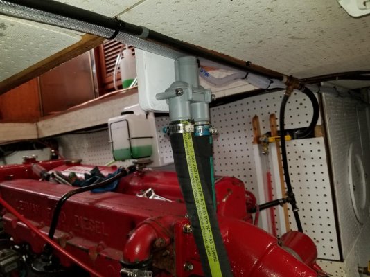
And we've got our vented loops installed for the new exhaust elbows. We are getting the exhaust coming out of the water lifts all the way up to the engine room ceiling, so I think we've got good progress on the exhaust system. More on that when I can post a full set of pictures for it in the next week or two.

20190121_145316.jpg

Its good to see some improvements, some PM that I won't have to worry about for a while, and projects/repairs that were tear outs months ago going back together!
 

Latest posts

Back
Top Bottom