Seahorse Marine Diesel Duck Vibration - Advice needed

The friendliest place on the web for anyone who enjoys boating.
If you have answers, please help by responding to the unanswered posts.
Professional Boat Builder issue number 74, page 85, has an article about vibration which is pretty good. The article is from 2002 and most of the company websites listed at the end of the article are no longer valid, one website is still available, http://www.balmacinc.com/products/digital-vibration-meters#spucontent205

This company sells devices but not sure how much they cost. But they do have some interesting information on the FAQ page, FAQs, that has some helpful documents, including a chart that talks about how to interpret the test results,http://www.balmacinc.com/downloads/SeverityChart.pdf.

Not sure it is worth the OP buying one of the devices but some of this information might be helpful to know when hiring someone. The company might have some contacts in HK as well.

The article mentions using vibration sensors to equipment that might help detect vibration before they become an issue or out right failure. Interesting idea.

Later,
Dan
 
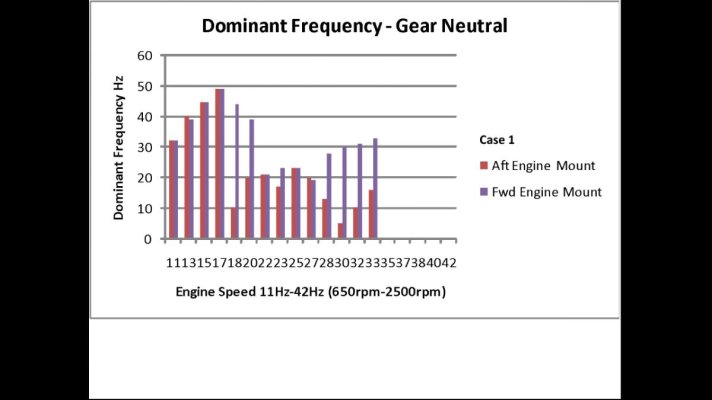
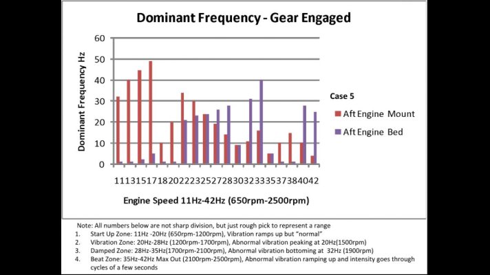
When I looked at the graph in Post 72 of this thread I was reminded of two very dramatic structure vibration problems from my experience in industry (not boats or marine). Both of these problems resulted from very small oscillating forces being applied to a structure at, or close to a natural vibration frequency of the structure. To understand the problem required identifying the source of the small oscillating force, and the natural frequencies of the structure.

What caught my eye in the graph in Post 72:

A. The dominant vibration frequency at the engine mount and the thrust bearing in the two rpm ranges where the vibration is most prominent are generally the same, and at the engine rpm frequency. (one exception, all data seems to have to do that to keep us humble) If the oscillating force was due to misalignment of the shafts, eccentricity of the couplings, bent shaft, or whip due to one of these things the thrust bearing dominant frequency should be 1/3 the engine speed. The gear ratio is 3:1 and the prop has three blades, so this means any oscillating force produced by the relationship with the prop and the hull or deadwood would be at engine speed. All of this leads me to tend towards the engine or the hydrodynamic interference between the prop blades and the hull or deadwood as the source of the oscillating force. I also note from the facts presented that the prop is one of a few unique elements of this installation.

B. The sympathetic vibration caused by the application of an oscillating force to a structure can happen if the natural frequency is a multiple of the frequency of the force. It appears from the graph that the higher frequency where the force and natural frequency may be aligned are about double the lower, with the higher being just above the maximum rpm of the engine. This would help to confirm that the issue is not just the magnitude of the oscillating force, but also the natural frequency of the structure it is applied to. This is valuable to know as it gives you two ways to mitigate the effect, reducing the force, or changing the natural frequency of the structure.

An amateur in an armchair half way around the world from the problem has no chance of solving it, but with that qualifier here’s my input.

I suspect that the source of the oscillating force is the propeller, with the oscillation caused by the interaction between blades and hull or deadwood. I believe the second propeller tried was also a 3 blade, so would have changed the forces, but not the frequency. If the source was the engine the structure would not be absolutely smooth in neutral.

I suspect that the structural element with the troublesome natural frequency is the reinforced plate diaphragm welded to the engine beds that the thrust bearing is bolted to. It could also be the unsupported shaft, but moving the center bearing should have made some difference if that were the case.

The two things I would try first to mitigate the problem:
Add some rubber washers on both sides of the plate where the thrust bearing is bolted. Several have suggested this. The goal here is to reduce the oscillating force.
Weld some angle iron braces between the engine bed and the diaphragm plate as close as possible to the thrust bearing, transferring the axial force on the diaphragm directly to the engine bed stringers. Stiffening this plate has also been suggested by others. The goal here is to change the natural frequency.

So says the armchair amateur on the other side of the world. I agree that a competent structural vibration analysis with current analytical tools would have a high probability of success!

I think the OP was on the right track with his questions below in post 72.

Bill


“4. The graph below show dominant vibration frequency measured below engine mount and below thrust bearing (a lot more data available for those interested) . I added some notes which are extracted from the starting post of this whole thread. These describe the "subjective" vibration sensation I felt, and there seems to be some kind of correlation that if engine rpm is transmitted through engine mount and to thrust bearing, I would sense the vibration. But isn't that obvious, that the power that drives the vibration has to come from the engine. But interestingly is:


5. Why engine frequency was not transmitted to below thrust bearing at the quiet range (per my subjective sense) ? Was there some kind of "destructive interference" to counter against engine power ? Anyway I am not to ask anyone for an answer, but just a question in my mind.”
 
I have not done a ton of marine shaft work, but done some other vib analysis. There is a Fluke model 805 handheld vibration meter that I have used in the field. Very easy to get measurements. Also, you did a topside run with wheel on. I was thinking a wet run with NO wheel on, thru all RPM's would be telling. In water, the hull will rest at the "normal" position. Running with no prop should be very smooth, of course that does not result on any compressive loading of the shaft. So, if its shaking there, you know there is a power train issue.

I will look into the Fluke meter, though I doubt I can afford one, nor would it help much in the wrong (my) hand. Bill Kimley did ask me to look into hiring a professional, who would bring his/her own equipment.

I took the measurement with an Android phone while tied up in the water in an empty typhoon shelter.

I don't understand what you mean by "top side run with wheel on", "wet run with no wheel on". Could you elaborate ?
 
From a professional marine engineer friend....

"Having used professional vibration analysis firms over the years to diagnose problems like the OP presented, I can say with no reservations that chasing vibration issues by doing anything else in 2018 is truly a fool's errand. "!

Thank you for your comment.

I need to understand the concept of the appropriate vibration analysis which would apply to my boat.

As stated in earlier Posts/Replies, I am aware of an approach which I call "Calibrated Theoretical Model". Torsional vibration at various points of the drive train is predicted through a theoretical model. Then a sensor is placed (I was told only one sensor needed) near the engine end of the shaft, and the measured result is used to calibrate the theoretical model to identify the source of vibration. Then more sensor(s) can be used to confirm the source.

I feel this approach is more of a tool to eliminate resonance at design/construction stage. I would think in my already built boat, the measurement should not rely on a theoretical model.

Would you share some of your thoughts/experience on vibration measurement by professional boat vibration trouble shooter ? Can you recommend one as well ? I need to share this with Bill Kimley.
 
Such great feedback above. Regarding vibes only under load, let me interject one other possibility that I haven’t seen mentioned (apologies if I missed it). A decently balanced prop would spin exactly as you reported in the dry test, but under load in water, even a perfectly balanced prop would wobble if one of the three blades were not pitched as the other two. You already know that the bite of blades on the top stroke are moving through water of less density than the two that are moving in and out of their lower strokes. Add a bit less pitch on one blade and you’ve got a pretty strong encouragement for the shaft (especially if undersized or compromised in material) to bow up and down with each revolution, and getting worse as RPM’s (load) increased. Thanks to a well placed and sturdy cutlass, any resulting bow would likely occur between the cutlass and the next bearing, likely inside the shaft log itself. This, just to add to your considerations.

I am getting a free lesson here. If I am a smart student (and I am not), amd I correct I would start looking at the shaft ...

On the other hand as stated in an earlier Post/Reply, in the very last (4th) attempt, the Hong Kong Sub-Contractor did insert Whip Bearing No. 2 from the aft, which got stuck about 2 ft from the Cutlass Bearing. Though Bearing No. 2 should not have been inserted as I realize now, it was there as an additional force to constrain the shaft against the force you mentioned above. In your opinion what would happen ?
 
I've just caught up with this thread and my sympathies to the OP. For what it's worth:-
We have a smaller Duck (DD44) that for years had noise and vibration, though not severe. In the end I dumped the Carden drive and replaced it with a stub drive shaft and an aquadrive unit. In checking we found that the prop shaft flange was not centred and had worn the shaft bearing - both were replaced. Finally we found that the rudder bearing was worn and creating it's own rumble, that had been thought to be a transmission noise - that was replaced. Finally peace. Now we have a smooth operating piece of machinery. Good luck with your engineering.

Thank you for sharing your experience. I believe Destiny is an earlier duck built by Seahorse. Are you the original owner ?

Doing away with Cardan shaft seems to be a drastic (and risky) move. I know two DD462 owners did that because the shafts was corroded and in North America, boat yards are more familiar (therefore less risky) with direct shaft/transmission coupling.

In your case what led to the decision to remove Cardan shaft ? To solve the vibration problem by changing configuration, or the need to follow local approach in shaft replacement ?

Also if you don't mind so I can have a reference, what is your engine power, original shaft length, shaft diameter ? How far is the whip bearing from the thrust bearing ?

Thank you in advance.
 
For a variety of reasons, running the engine and shaft out of the water really isn't a valid analysis. A dial indicator on the shaft at the coupling initially, will be a very valuable test. The shaft is turned slowly by hand, ideally with the boat afloat.

The first photo, of a coupling, in this article The Ins and Outs of Engine and Shaft Alignment Part I | Steve D'Antonio Marine Consulting with the laser in the middle, shows the pilot pushing on the transmission flange (it's damaged). It interfaces with a recess on the shaft coupling. If these are not centered, you will have vibration.

The bore or hole in the shaft coupling must, for obvious reasons, be centered in the coupling, as must the pilot bushing. If not, the shaft rotation will not be smooth, it will revolve about an axis rather than rotate on it.

Once again, a professional analyzing the vibration, preferably onsite but remotely if necessary, will be money well-spent.

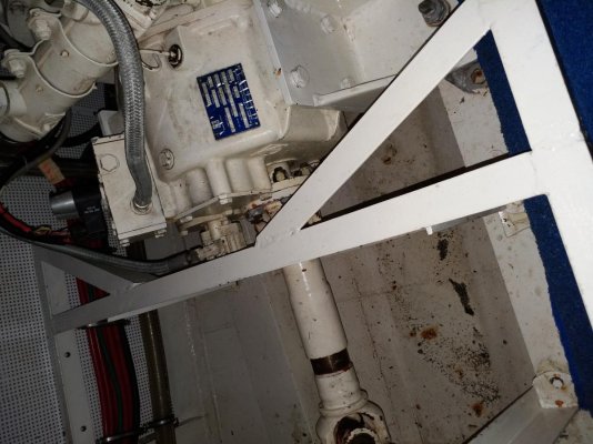
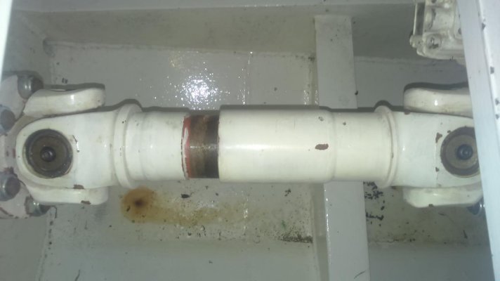
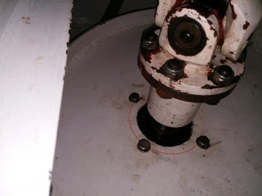
I did hear Bill's stray dog joke;-) BTW, there's a photo of a DD under construction in this article, it was taken in 2015. A Boat Buyer’s ‘Top Ten’ Guide to a Pre-Offer Evaluation Part I | Steve D'Antonio Marine Consulting During that yard visit the vessels I reviewed had conventional, double universal joint shafts and thrust bearings, shown here. Is yours not like this?

Thank you for your reply. I will look at the picture in the article and see if/how my boat has any similar issues.

Yes the Cardan Shaft in your picture is what I have, though mine looks a bit tattered out as delivered. As stated in another Post/Reply, I plan to re-check for correct phasing, the play between the spline, and the linear slide between the two halvess
 

Attachments

  • 20180612_153231.jpg
    20180612_153231.jpg
    140.5 KB · Views: 49
  • DSC_0467.jpg
    DSC_0467.jpg
    50.1 KB · Views: 56
  • 20180610_123558.jpg
    20180610_123558.jpg
    84.9 KB · Views: 52
Thank you for sharing your experience. I believe Destiny is an earlier duck built by Seahorse. Are you the original owner ?

Doing away with Cardan shaft seems to be a drastic (and risky) move. I know two DD462 owners did that because the shafts was corroded and in North America, boat yards are more familiar (therefore less risky) with direct shaft/transmission coupling.

In your case what led to the decision to remove Cardan shaft ? To solve the vibration problem by changing configuration, or the need to follow local approach in shaft replacement ?

Also if you don't mind so I can have a reference, what is your engine power, original shaft length, shaft diameter ? How far is the whip bearing from the thrust bearing ?

Thank you in advance.

We took professional advice from a company in Malta who are more experienced in big yachts and ships than I am in terms of transmissions.
My own feeling was that the Carden drive looked like it had come off of an old Chinese truck and because this was an early model duck, somebody had decided to add it in. Incidentally (we are 2nd owners - looking for a 3rd) I did find in the 'parts' box a direct coupling shaft that seemed to suggest that originally the shaft was direct coupled to the gearbox.

The original Carden was worn on one of the bearings and we'd earlier replaced it with another which hadn't helped. My own feeling was that the Carden was a lot of metal on metal which is only going to increase/ amplify any noise or rumble in the sytem.

Tech info: Engine is JD 120HP 4Cyl, The is no intermediate/ whip bearing, shaft length - not sure I'd guess about 3.5M (10ft) 1 3/4" dia. For extra info we dropped the shaft a few years back, to change the cutlass bearing, check for shaft alignment and check prop balance.
 
When I looked at the graph in Post 72 of this thread I was reminded of two very dramatic structure vibration problems from my experience in industry (not boats or marine). Both of these problems resulted from very small oscillating forces being applied to a structure at, or close to a natural vibration frequency of the structure. To understand the problem required identifying the source of the small oscillating force, and the natural frequencies of the structure.

What caught my eye in the graph in Post 72:

....................

Thank you so much for taking the time, and for your suggestions. It would take me a lot of time to think through, but perhaps the corrective actions could be tried before I understand the analysis.

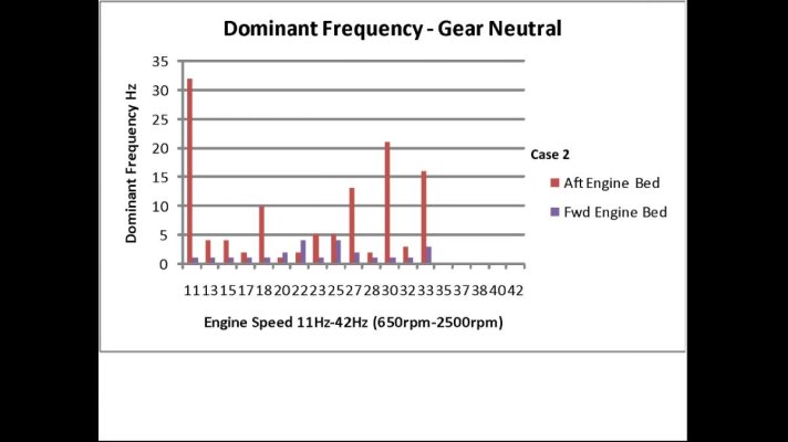
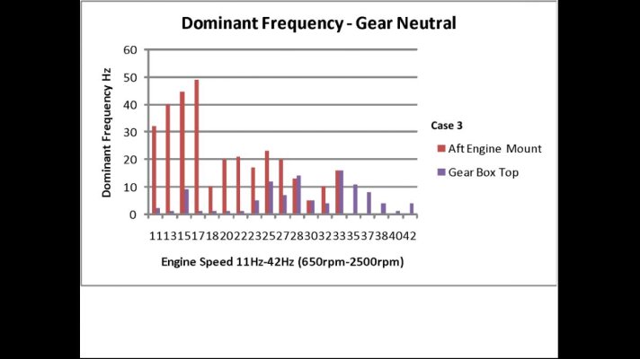
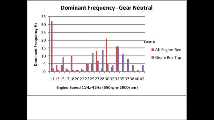
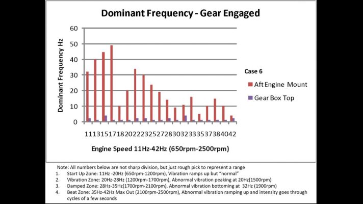
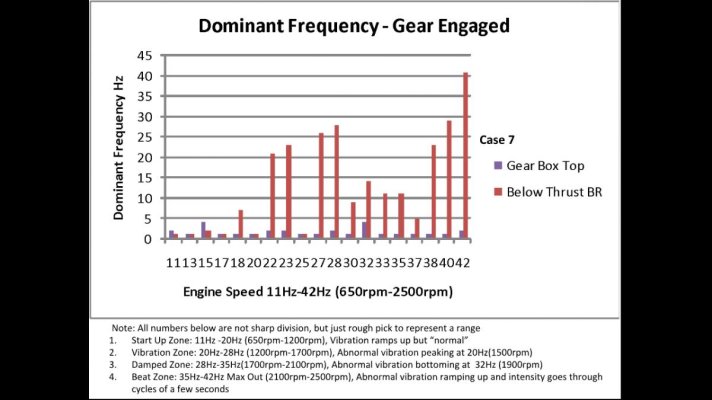
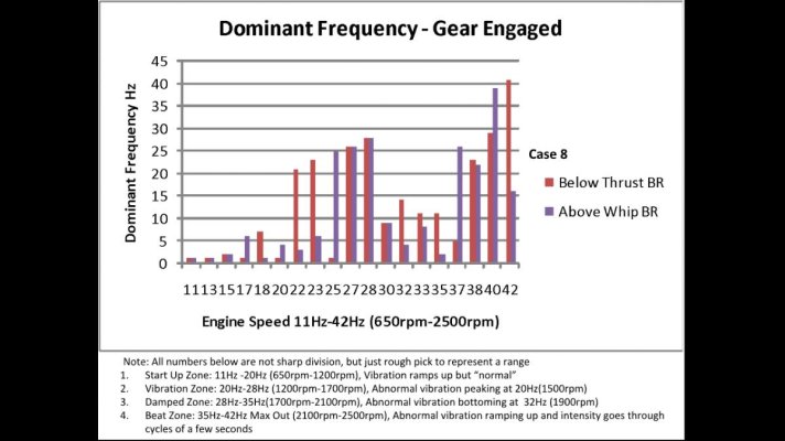
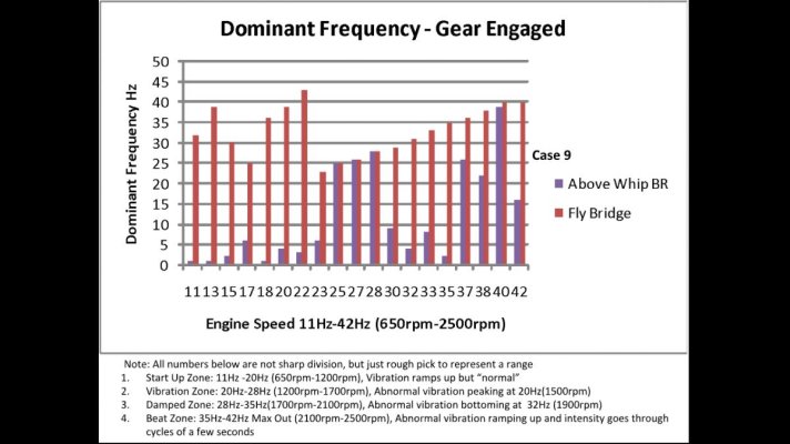
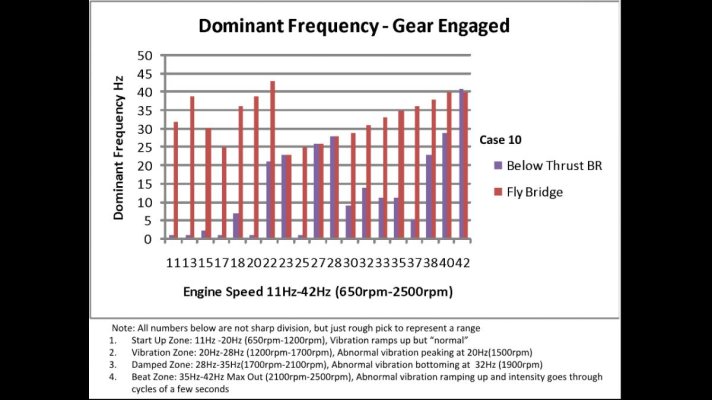
For your interest, and since it is so easy to generate graphs, all the dominant frequency data is graphed below, ONLY FOR THE CURIOUS. OTHERS PLEASE DO NOT WASTE YOUR TIME. For the sake of standardizing the language, I define vibration frequency ranges according to my SUBJECTIVE sense in four:

1. Start Up Zone (from 650rpm to Approx 1100/1200rpm) where vibration increases with rpm, but could be considered as "normal".

2. Vibration Zone (from 1100/1200rpm to about 1700/1800rpm) where vibration ramps up and has a peak at about 1500rpm. Everything rattle and the floor on fly bridge jumps

3. Damped Zone (from 1700/1800rpm to 2100/2200rpm) where vibration intensity reduces to something like 1200/1300rpm

4. Beat Zone (from 2100/2200rpm and upward, engine max out at 2500rpm) where the vibration intensity goes up and down regularly everyone few seconds, and worse than Vibration Zone.

There is still the maximum intensity data I may or may not even know how to graph. The Android App I used only measure maximum intensity and corresponding frequency. I just found one which generates the whole frequency spectrum and intensity at the same time. Hmmm... I dread going to that typhoon shelter in the middle of nowhere ...

All this said, I want to acknowledge some previous Posts/Replies, that an Android is not a real vibration detector, the whole concept of vibration measurement is not understood by me, that fundamental trouble shooting principles and actual fixes are still the most important.
 

Attachments

  • Screenshot_20180617-174809.jpg
    Screenshot_20180617-174809.jpg
    60.8 KB · Views: 51
  • Screenshot_20180617-174820.jpg
    Screenshot_20180617-174820.jpg
    58.4 KB · Views: 49
  • Screenshot_20180617-174828.jpg
    Screenshot_20180617-174828.jpg
    59.4 KB · Views: 50
  • Screenshot_20180617-174835.jpg
    Screenshot_20180617-174835.jpg
    60.3 KB · Views: 56
  • Screenshot_20180617-174846.jpg
    Screenshot_20180617-174846.jpg
    88.5 KB · Views: 51
  • Screenshot_20180617-174858.jpg
    Screenshot_20180617-174858.jpg
    86.8 KB · Views: 52
  • Screenshot_20180617-174908.jpg
    Screenshot_20180617-174908.jpg
    90.6 KB · Views: 51
  • Screenshot_20180617-174917.jpg
    Screenshot_20180617-174917.jpg
    91.9 KB · Views: 50
  • Screenshot_20180617-174926.jpg
    Screenshot_20180617-174926.jpg
    96.9 KB · Views: 48
  • Screenshot_20180617-174935.jpg
    Screenshot_20180617-174935.jpg
    96.4 KB · Views: 54
Some suggestions passed to me from a tech savy friend.....

" Advanced Mechanical Enterprises Rich Merhige was my go to guy when I was technical superintendent for Camper & Nicholsons. I have also worked with Chris at High Seas for shaft and rudder bearing work but vibration analysis is not his forte'. Vibration analysis is like a medical specialist, all doctors have a basic MD but you don't go to a knee surgeon for a heart problem.

I find it incredible that so many people are tossing in suggestions to buy this or that piece of instrumentation or rubber washers or some other means to throw good money away chasing ghosts. I guess if the OP wants to make a hobby out of amateur vibration sleuthing he could follow the advice of the many but if he wants to cure the problem there is only one way to do it quickly and economically.

Considering the builder and location and the way those folks work it probably is a kluge of bad workmanship, misalignment, and wrong parts but like most marine engineering problems, just throwing parts at it will probably be very expensive and equally frustrating. "
 
A phone is not going to give you accurate information you need to find the problem. The vibration sensor should be firmly attached to the point of measurements. The one we used at my last job had a very strong magnet to hold it.

When we checked for vibration. We checked both horizontal and vertical front and rear of the engine and generator. From what you've posted it doesn't sound like an engine problem but more of a gear or shaft issue.

If you have the means to get stuff from Amazon. They have some decent vibration test meters that you could get the data and have someone state side analyze it.

TES 3100 VIBRATION METER https://www.amazon.com/dp/B01LYR0W6X/ref=cm_sw_r_cp_apa_FKNjBbM1ZX3DX
 
When I looked at the graph in Post 72 of this thread I was reminded of two very dramatic structure vibration problems from my experience in industry ..........

I suspect that the source of the oscillating force is the propeller, with the oscillation caused by the interaction between blades and hull or deadwood. I believe the second propeller tried was also a 3 blade, so would have changed the forces, but not the frequency. If the source was the engine the structure would not be absolutely smooth in neutral.

.........”

I forgot to correct you on the fact. The boat was delivered with a 3 blade Max Prop (folding). As Bill Kimely suspected it might have been the cause of the vibration, a fixed FOUR blade Prop (ie. the second prop) was installed. The "second prop" is not a 3 blade.

Also at the time Bill did not have a equivalent size four blade prop, and for the sake of trying out a fixed four blade, he sent me a smaller four blade which at best generated 50+% of what the engine was capable of. The vibration became less, but still very evident and abnormal, even at only 50% power.
 
Last edited:
Professional Boat Builder issue number 74, page 85, has an article about vibration which is pretty good. The article is from 2002 and most of the company websites listed at the end of the article are no longer valid, one website is still available, http://www.balmacinc.com/products/digital-vibration-meters#spucontent205

This company sells devices but not sure how much they cost. But they do have some interesting information on the FAQ page, FAQs, that has some helpful documents, including a chart that talks about how to interpret the test results,http://www.balmacinc.com/downloads/SeverityChart.pdf.

Not sure it is worth the OP buying one of the devices but some of this information might be helpful to know when hiring someone. The company might have some contacts in HK as well.

...

Forgot to mention another idea I had when I posted the above information.

Are there any tool rental companies in Hong Kong? There are places in the US that rent tools/equipment that one needs infrequently. It might be cheap enough to rent a tool and see what information it provides.

One rental company I have used in the past did not want their equipment to leave the US but they said they might allow it. I suspect they would just charge me for the equipment, and return my money, minus the rental fee, after their property was returned.

Once one gets the data, how does one interpret the data? The tool website linked above has some information on analysis but will that be enough? That might require an expert. If said expert is not available locally, the OP might be able to provide the data to an overseas expert if they can get the instrument locally.

Later,
Dan
 
I'm a bit Rusty at vibration testing. So as best I remember I posted some info. Also the chart posted looks like a pretty good way for you to determine good vibration reading for a bad one.

As bad as it sounds like. It should be very apparent on the meter. Just look for the greatest velocity and mil's. Also the vibration itself will point you in the right direction. Run the boat at the point of greatest vibration so it will stand out when you look at the data. Take notes on the exact rpm you took the readings at. You will need to figure out what components are turning at the same hz as the vibration.

Spent a couple of days drafting some ideas for Bill Kimley to review, and hopefully he would support (jigs, TES3100 and other equipment, some muscle power, pizza delivery by Sampans ?) for a typhoon sea trial, and during actual boat lifting to replace the shaft in Hong Kong.

In stepping back and looking at all the graphs in Post #99, they look as if they tell what vibration is transmitted among members of the drive train. Interestingly to myself as a layman:

1. The Android App I used only measured dominant frequency (frequency at max acceleration). New Apps now can record the vibration over the full frequency spectrum.

2. Dominant frequencies at high rpm (where I felt the worst vibration) are essentially all high frequency, which is not detectable by human sense of touch (a few Hz I believe). This might be an ignorant question: How does 800rpm gear box/shaft frequency (ie. 2400 engine rpm) manifest itself into a few Hz, and how to find evidence that say, the 800rpm component detected on fly bridge is indeed the excitation force of the few Hz vibration sensed by me ?

3. In addition to engine rpm and shaft rpm, I should also be looking for prop-blade passing frequency (shaft rpm x 3). It happened that the full size max prop was a 3 blade which can be masked by the gear box reduction ratio of 3:1. Now with a half power 4 blade prop installed, I might see something different.

Will visit Bill Kimley next week to exchange some ideas. Hopefully he won't throw me out.
 
I'm sorry to hear about the issues with Bill and Stella. I've been to this yard and must say it's among the most interesting I've ever visited, if for no other reason than Bill's train set.

Seems obvious, and perhaps already mentioned, but has the shaft been checked for straightness? And, has it been confirmed that the shaft coupling bore is centered, and that the coupling pilot bushing is centered in the recess in the coupling with which it mates? Is the shaft tapered at the coupling end? Ideally it should be.

I have had experience with locally made couplings in Asia on several occasions not being on center. All of these issues can be easily identified using a dial indicator. To fully and properly check shaft straightness it would need to be pulled from the vessel, however, determining if the shaft is centered in the coupling or if the coupling pilot is correct could be done without shaft removal.

It's also worth noting that misalignment, because it is constant, rarely causes vibration. Eccentrics in running gear lead to vibration.

I've also had something as simple as a defective, new motor mount cause serious vibration. The list of possibilities, especially with a system that has some unusual features, is nearly endless. You need professional support or you could chase this endlessly. I've contracted with vibration analysts who, in a few hours, can literally point to the offending source.

The outfit I profiled in this article is among the best in the business when it comes to vibration analysis, and repair (they are in South Florida). They may be willing to consult for you, from afar. Otherwise, a known marine vibration analyst in the HK area may be your best bet.
http://stevedmarineconsulting.com/wp-content/uploads/2014/03/Shaft-Alignment-159-02.pdf

Read through the article and will communicate with Chris Brown. I am also investigating the use of the surveyor's scope with the boat lifted. Very nice article ! Will have to spend some time to go through other articles you referenced in later posts.
 
If you have a steel shaft log, what purpose does the fiberglass tube serve?

I've done something similar to what you propose. Buy a hole saw of the appropriate diameter, remove the middle part and weld a pipe through it. This acts as the guide and the drive. A good quality hole saw will be "bi-metal", that is have high speed steel hardened teeth welded to a mild steel shell. The trickiest part is filling epoxy around the new tube without numerous gaps. The way to do that is to seal the low end (I used a turned piece with orings) and pump the epoxy in from the low end with a grease gun or similar tool. This will force it along the tube all the way to the other end, pushing the air ahead. Two strategies: use a thin epoxy so that it will run around the diameter as it goes, or fairly thick so that the pump pressure pushes it along which should also fill around the tube if the gap is relatively small. Do it on a cold day :)

But you have a steel boat. If a tube is needed, why not weld in a stainless steel one?

How big a job was it where you used the hole saw, e.g.:

Length, diameter, wall thickness of the tube and epoxy removed;
How long did it take and how many hole saw bits were worn out

etc.etc.

Would really appreciate you sharing the experience. Not much detail of anyone doing this when I googled.
 
If you go to the last picture of this post:

Hauled Out - M/V Mahalo

You'll meet Jeff Fritges. Jeff is contracted by the builder of our boat to assess all rotational components. But he does more than that. Over a meal with him in Shanghai I was fascinated to learn the history of vibration analysis, which got its start in the Navy. I won't go into the whole history here but it's quite fascinating. And it is awesome that it has progressed from the Navy, to commercial ships, to the cruise ship industry, and is now available at our recreational boat level.

Jeff travels with $60k of test equipment. I would think Jeff could quickly get to the source of the issue here along with the remedy required.

Unfortunately he is sort of between web providers at this moment, so his previous website is unavailable. But his email is jeff@truephase.net. Tell him Bob of Mahalo sent you.
 
How big a job was it where you used the hole saw, e.g.:

Length, diameter, wall thickness of the tube and epoxy removed;
How long did it take and how many hole saw bits were worn out

etc.etc.

Would really appreciate you sharing the experience. Not much detail of anyone doing this when I googled.
I've done this only through several inches of glass laminate. I've seen it done to free keel bolts in (fiberglass) deadwood, about 18 inches. There is no reason it would not work in a large and long hole, with a couple of caveats: you need to get the dust and swarf out. In a very deep hole I'd be looking at some way to flush it with water as you cut, either from the end you are working or the other. Otherwise you will be withdrawing the bit very frequently to evacuate it. Second, on a large diameter, you are going to need a large drill motor to drive it, and a large gentleman or two to hang onto that motor. Going through just epoxy, or even epoxy thickened with glass floc, will be easier than laminate, and the saw will last longer.

I've not seen exactly what you are dealing with so this is speculation on my part, but worth investigating.
 
problems with a holesaw...

I've done this only through several inches of glass laminate. I've seen it done to free keel bolts in (fiberglass) deadwood, about 18 inches. There is no reason it would not work in a large and long hole, with a couple of caveats: you need to get the dust and swarf out. In a very deep hole I'd be looking at some way to flush it with water as you cut, either from the end you are working or the other. Otherwise you will be withdrawing the bit very frequently to evacuate it. Second, on a large diameter, you are going to need a large drill motor to drive it, and a large gentleman or two to hang onto that motor. Going through just epoxy, or even epoxy thickened with glass floc, will be easier than laminate, and the saw will last longer.

I've not seen exactly what you are dealing with so this is speculation on my part, but worth investigating.

Most holesaws have a limited depth to about 2-3 inches, and specialized ones can go to about 8 inches. At that point, you'll have to remove the plug and continue on. Since you already have a driveshaft in place, why not built a forstner bit around a tube that ID is slightly larger than the driveshaft and use the driveshaft as a guide. The forstner bit will chew through whatever is there and auger it out.
 
Most holesaws have a limited depth to about 2-3 inches, and specialized ones can go to about 8 inches. At that point, you'll have to remove the plug and continue on. Since you already have a driveshaft in place, why not built a forstner bit around a tube that ID is slightly larger than the driveshaft and use the driveshaft as a guide. The forstner bit will chew through whatever is there and auger it out.

I think DDW, you and I are all thinking along the same line:

A reaming tool is precise by maintaining its own center line, but cannot do so over a long length. If we let go the precision in my case, the stern tube case the shaft and stern tube already define a long center line and relieves the burden from the tool. The tool may rely on this center line and chew out the fiberglass stern tube and surrounding epoxy, and the precision may be picked up at the re-install stage of the stern tube instead. Thank you both for suggesting hole saw and forstner bit.

A Forstner bit as I understand relies on its outer diameter for centering. In this case that would be the 5" ID steel shaft log. Forstner bit then chews up the fiberglass tube and the surrounding epoxy, all within the 5" shaft log, and spits out the garbage. I hope it does not hurt the steel shaft log internal.

The hole saw with a thick wall can do the same, but relies on the shaft for centering, and the flat end has to be partially cut in order to allow material removal. A hole saw can also be pulled by the shaft (or a pipe of same diameter) with the entire shaft acting as a guide. I somehow prefer the full shaft guide approach, even though that degree of precision is probably not necessary. I cannot see how a Forstner bit can be pulled (only push).

I probably would go with the Forstner as it does not need to be modified. However I have been told by many, that gutting out the stern tube and surrounding epoxy is impractical, and it's better to precision ream the stern tube, even over its entire length. When I ask them why (all seasoned workers), none could articulate. Bill Kimley is the only person who would gut it out if something is wrong with the stern tube.

I think the whole thing comes to the material strength of fiberglass, surrounding epoxy, and steel shaft log. I have no clue as I am not a DIY type. If and when the time comes I need to do an experiment first. I hope:

1. The Forstner bit would wear it self out before damaging the shaft log (it should as it is meant for woodwork)
2. It would chew up Fiberglass and surrounding epoxy (some say the epoxy is very hard and would wear out the tool in a couple of minutes)
3. The epoxy would break off dry, and not turn into glue and gum to foul up the tool and the shaft log.

Comment from anyone who has worked with Fiberglass and epoxy ?
 
Last edited:
If you go to the last picture of this post:

Hauled Out - M/V Mahalo

You'll meet Jeff Fritges. Jeff is contracted by the builder of our boat to assess all rotational components. But he does more than that. Over a meal with him in Shanghai I was fascinated to learn the history of vibration analysis, which got its start in the Navy. I won't go into the whole history here but it's quite fascinating. And it is awesome that it has progressed from the Navy, to commercial ships, to the cruise ship industry, and is now available at our recreational boat level.

Jeff travels with $60k of test equipment. I would think Jeff could quickly get to the source of the issue here along with the remedy required.

Unfortunately he is sort of between web providers at this moment, so his previous website is unavailable. But his email is jeff@truephase.net. Tell him Bob of Mahalo sent you.

Thank you so much ! Will definitely contact Jeff. Tried a few based in USA, and no reply.
 
Forstner bit vs fiberglass & epoxy.

The Forstner bit can easily cut the fiberglass / epoxy resin. I would think it would not dull it as much as the grit found in an oak plank. Besides, it is tool steel and should hold an edge for quite a while. Many holesaws are simply stamped steel sheet over a form with teeth cut into the edges. Hitting the concrete ballast would dull it quickly, though.

Since this is a steel diesel duck, what would be the problem in taking a cut-off tool and cutting down one side of the hull, removing the concrete and shaft log, replace with new up-sized shaft log and welding in place to stringers or frames, and then fill with concrete or other ballast material before welding the removed hull side back where it came from? That would probably be easier to find a welder who could / would do that rather than the forstner bit approach. It it were my boat, and you knew for certain that the shaft needed to be up-sized, that's the plan I would choose.

Stu


I think DDW, you and I are all thinking along the same line:

A reaming tool is precise by maintaining its own center line, but cannot do so over a long length. If we let go the precision in my case, the stern tube case the shaft and stern tube already define a long center line and relieves the burden from the tool. The tool may rely on this center line and chew out the fiberglass stern tube and surrounding epoxy, and the precision may be picked up at the re-install stage of the stern tube instead. Thank you both for suggesting hole saw and forstner bit.

A Forstner bit as I understand relies on its outer diameter for centering. In this case that would be the 5" ID steel shaft log. Forstner bit then chews up the fiberglass tube and the surrounding epoxy, all within the 5" shaft log, and spits out the garbage. I hope it does not hurt the steel shaft log internal.

The hole saw with a thick wall can do the same, but relies on the shaft for centering, and the flat end has to be partially cut in order to allow material removal. A hole saw can also be pulled by the shaft (or a pipe of same diameter) with the entire shaft acting as a guide. I somehow prefer the full shaft guide approach, even though that degree of precision is probably not necessary. I cannot see how a Forstner bit can be pulled (only push).

I probably would go with the Forstner as it does not need to be modified. However I have been told by many, that gutting out the stern tube and surrounding epoxy is impractical, and it's better to precision ream the stern tube, even over its entire length. When I ask them why (all seasoned workers), none could articulate. Bill Kimley is the only person who would gut it out if something is wrong with the stern tube.

I think the whole thing comes to the material strength of fiberglass, surrounding epoxy, and steel shaft log. I have no clue as I am not a DIY type. If and when the time comes I need to do an experiment first. I hope:

1. The Forstner bit would wear it self out before damaging the shaft log (it should as it is meant for woodwork)
2. It would chew up Fiberglass and surrounding epoxy (some say the epoxy is very hard and would wear out the tool in a couple of minutes)
3. The epoxy would break off dry, and not turn into glue and gum to foul up the tool and the shaft log.

Comment from anyone who has worked with Fiberglass and epoxy ?
 
Are you saying that the whole length of your steel shaft tube is lined with a fiberglass tube? If that's the case you're not coring it out with a modded hole saw or forstner bit or whatever. Can you even buy a forstner bit that large?
Don't get ahead of yourself on this project. Hire a pro that knows what they're doing, figure out if you even need a larger diameter shaft. Even if you had to replace your existing shaft with one the same diameter made of the most expensive shaft alloy it'd still be way cheaper than trying to gut that fiberglass tube.
Just had an idea, this I'd be fun, if you had to get that fiberglass tube out and if it's held in with epoxy, epoxy doesn't like heat. Treat your shaft tube like a steam box, cap one end, attach steam generator to the other end, steam it for a few hours, or overnite. Most epoxies start to breakdown at around 140F, you should be able to get it considerable hotter than that, but not so hot you'd hurt your paint on the steel tube. See if you could beat it out far enough that you could grab one end, then start pulling.

Yes, the entire 5" ID steel Shaft Log is lined. Just to summarize the construction again:

1. The 2-5/8" ID x 3.34m Fiberglass Stern Tube holds the 2" Prop Shaft inside with the help of Cutless Bearing and Whip Bearing.

2. The 5" ID x 3.24m Steel Shaft Log hols the Fiberglass Stern Tube, with the gap in between the two tubes filled by epoxy.

I am just planning for the worst case scenario where the Stern Tube needs to be enlarged. At this point I think that scenario is very unlikely (will get into that and latest progress later).

For worst case scenario I thought about opening up the side of the keel and get rid of the whole thing: the concrete ballast, the shaft log/stern tube, then re-weld, re-install, re-fill. I was told the re-welding heat is going to distort everything.

The suggestion of releasing the epoxy by heat is interesting, assuming it does not distort the shaft log. In fact we can apply heat directly on the shaft log, which is in direct contact with the epoxy. Hopefully the epoxy wont expand. All that need to be verified by an experiment, if it becomes necessary. I am more optimistic now it won't.
 
A good hole saw is bi-metal, that is high speed steel teeth welded onto the mild steel barrel. The teeth will last longer than a Forstner (which only has two). And much cheaper to start with. In addition, hole saws fit inside each other, so you can add two or more to take out whatever wall thickness you want. Modifying them is relatively easy compared to a Forstner. You just turn out the center to the size of your guide, slide it on the guide, and weld in place.

Epoxy will not wear out the tool quickly. Fiberglass will dull it though - fiberglass will dull even a carbide tool quickly. Even a dull bit will cut fiberglass, as it sort of tears it apart. But I'd count on using a few of these. A Forstner bit has one advantage, it spits the swarf out behind it, giving you a better chance of evacuating the chips. A hole saw tends to contain them inside, or the teeth get clogged, so you must withdraw to clear. That's why I suggest flushing with water as you go. This will also keep the tool and log cool. Any drill you use in there is going to get hot fairly quickly

Epoxies soften at around 150F, but they don't liquify and run out at that temp, just begin to get soft. The thing I would worry about is getting it soft enough to collapse or distort but not remove, now you have a bit of a mess as it can't be used as a guide to drill out.
 
The Forstner bit can easily cut the fiberglass / epoxy resin. I would think it would not dull it as much as the grit found in an oak plank. Besides, it is tool steel and should hold an edge for quite a while. Many holesaws are simply stamped steel sheet over a form with teeth cut into the edges. Hitting the concrete ballast would dull it quickly, though.

Since this is a steel diesel duck, what would be the problem in taking a cut-off tool and cutting down one side of the hull, removing the concrete and shaft log, replace with new up-sized shaft log and welding in place to stringers or frames, and then fill with concrete or other ballast material before welding the removed hull side back where it came from? That would probably be easier to find a welder who could / would do that rather than the forstner bit approach. It it were my boat, and you knew for certain that the shaft needed to be up-sized, that's the plan I would choose.

Stu

Thanks for the comment. Please see reply in Post #118
 

Latest posts

Back
Top Bottom