sean9c
Guru
I think you're correct, with most of the shaft in the tube and you don't know if the tube is straight, the best option is only one bearing in the tube, the cutless at the rear. Problem now is that if your going to try and support that shaft with just the cutless and thrust bearing and you want to stay with a 40x unsupported length you're looking at a 3" shaft.
So it sort of looks like your original shaft is way undersize for the unsupported length, putting your whip bearing in the tube likely didn't help, either because the tube isn't straight or the tube and shaft don't have the same centerline and you've caused a misalignment. So maybe you went from a vibration caused be too much span between bearings to one caused by a bent shaft.
I was also thinking that it would be interesting to put dial indicators on the spinning shaft and see if there was any runout. But then figured that there is likely to be some and then you have to figure out how much is acceptable. Not sure how you do that.
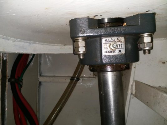
Also looking at the pictures again it doesn't appear that there is any provision for moving the thrust bearing on it's plate. With the original set up with just a cutless and this bearing you didn't really need to move it, the bearing in the plate will take up misalignment. Adding a intermediate bearing you would then have 3 points that have to be in alignment, so you will have to have a provision for moving the thrust bearing on the plate. It'd be interesting to know that now that you have the whip bearing in the tube what would happen if you unbolt the thrust bearing from the plate, you'd have to take the carden shaft off first, but I bet the thrust bearing moves when you take the bolts out. Bet you've put a bow in the shaft with the whip bearing.
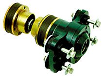
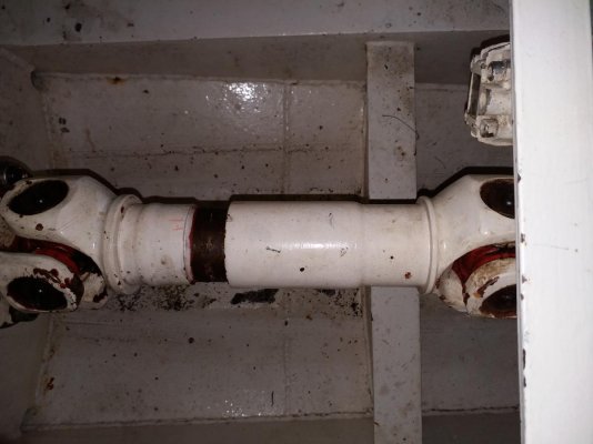
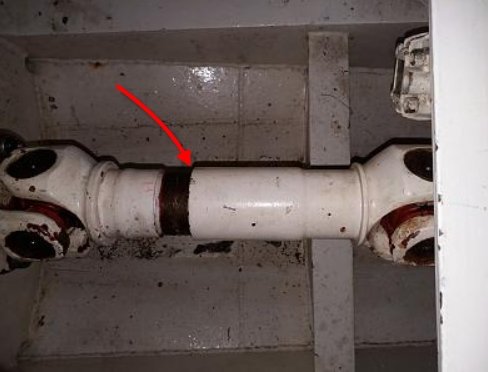
Another thing to look at is the carden shaft, carden joints can only take misalignment in one plane. Usually these things are used when your shaft angle and engine angle are different. But then was has to happen is that you need to know that your engine centerline lines up with your prop shaft centerline. That's on the vertical axis, basically if you are standing looking down on your engine and shaft they have to be in a straight line
You know, if this was my boat, I'd be looking to see if I could cut that shaft tube off short enough that I could put an intermediate bearing on a separate mount ahead of the tube.
So it sort of looks like your original shaft is way undersize for the unsupported length, putting your whip bearing in the tube likely didn't help, either because the tube isn't straight or the tube and shaft don't have the same centerline and you've caused a misalignment. So maybe you went from a vibration caused be too much span between bearings to one caused by a bent shaft.
I was also thinking that it would be interesting to put dial indicators on the spinning shaft and see if there was any runout. But then figured that there is likely to be some and then you have to figure out how much is acceptable. Not sure how you do that.
Also looking at the pictures again it doesn't appear that there is any provision for moving the thrust bearing on it's plate. With the original set up with just a cutless and this bearing you didn't really need to move it, the bearing in the plate will take up misalignment. Adding a intermediate bearing you would then have 3 points that have to be in alignment, so you will have to have a provision for moving the thrust bearing on the plate. It'd be interesting to know that now that you have the whip bearing in the tube what would happen if you unbolt the thrust bearing from the plate, you'd have to take the carden shaft off first, but I bet the thrust bearing moves when you take the bolts out. Bet you've put a bow in the shaft with the whip bearing.
Another thing to look at is the carden shaft, carden joints can only take misalignment in one plane. Usually these things are used when your shaft angle and engine angle are different. But then was has to happen is that you need to know that your engine centerline lines up with your prop shaft centerline. That's on the vertical axis, basically if you are standing looking down on your engine and shaft they have to be in a straight line
You know, if this was my boat, I'd be looking to see if I could cut that shaft tube off short enough that I could put an intermediate bearing on a separate mount ahead of the tube.

")