More solar questions....

The friendliest place on the web for anyone who enjoys boating.
If you have answers, please help by responding to the unanswered posts.

dhays

Guru
Joined
May 26, 2015
Messages
9,045
Location
United States
Vessel Name
Kinship
Vessel Make
North Pacific 43
I have been hijacking other threads so I decided I would start my own.

y'all have been very helpful in improving my understanding. I do have a few more questions and really hope you don't mind.

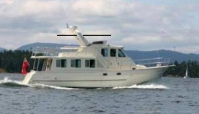
Situation: I am looking to place one 265w solar panel on my PH roof. Only one panel because that is all that I can conveniently fit on my boat.

A comment that psneed made in a solar thread a while ago has stuck with me. He said something along the lines that while his solar system may not be "perfect" it works well for him. Mathew 5:48 notwithstanding, I don't need to get a perfect system, just something that will help me keep the batteries charged when we stray further from home.

1. Placement of controller.
My limited understanding is that the charge controller should likely be located near the batteries as opposed to near the panel. The panel will put out higher voltage than the charge controller and so current from the panel to the controller will be less than from the controller to the battery. Putting the controller next to the battery means a shorter run for the larger wire needed for the higher current and using a smaller AWG wire for the run from Panel to controller. I think I would use 8 AWG from panel to controller in this scenario.

I would like opinions on another option. There is a DC panel in the PH. There is a 2/0 (maybe a 1/0 I will need to check) cable running from a bussbar there to the battery bank. Couldn't I just connect the controller output to that? This would make installation a lot easier. Instead of running 8 AWG wire from the pilothouse roof to the aft lazarette, I could just run the wire from the panel to the controller in the PH and connect the controller output to the bussbar.

Unless I am missing something, this should charge the batteries just fine. The only downside would be that I would't have temperature monitoring of the batteries. However, the batteries are in an aft space that is shaded and sitting in water that is normally right around 50 degrees. Also, the max that the charge controller would be putting out would be 30 amps, nothing like the 125 amps that my shore charger kicks out.

2. Running wire through the PH roof.
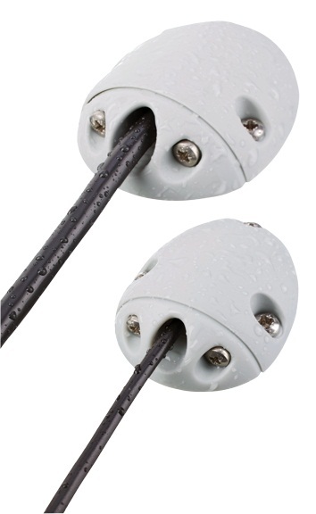
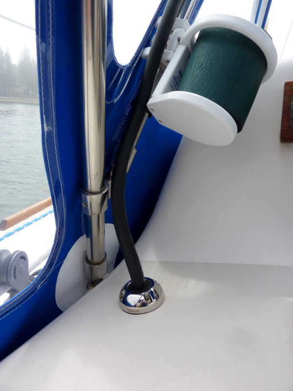
This is a simple and simpleminded question. I will need to run the panel wire through the PH roof. How do I do that without creating leaking issues?
 
If you have a significant (more than a half volt) voltage drop from the solar panel to the controller, no big deal. The panels are putting out lots of voltage and all you are losing is a little power, not performance.

But a half volt drop in the wire from the controller to the batteries is a big deal. The controller is adjusting its voltage output based on its charging algorithm. If you have a 0.5 volt drop then the battery is seeing less voltage than the algorithm expects so your batteries will not charge as fast as they should.

I would try to keep the voltage drop at 0.2 volts or less in the controller to battery circuit, whatever size is required to do that based on the distance.

As you note you can hook your controller up anywhere in its circuit as long as the wiring is large enough to keep the voltage drop low as above. The main DC panel is a good spot. You can often use a spare breaker and back feed the battery through it. Or tie in to the main buss through a properly sized fuse. Size the fuse or the breaker so it protects the wire to it.

David
 
Thanks David, that makes sense. Even with the connections (which I can clean) I think I will get less voltage drop using the large cable connecting the DC panel to the batteries.

I’ve read the same suggestion you just gave about “back feed the battery through a breaker”. To be honest, I don’t fully understand what that means. My guess is that it means the charge controller feeds DC back towards the battery from the panel that normally is getting DC current fed to it from the batteries.

If the controller will put out a max of 30amps, that means that I would need a spare 30amp breaker to connect between the charge controller and the positive buss?
 
My solar is wired exactly as you are proposing. It works great.

You can use a panel breaker, or a separate fuse or breaker.
 
My solar is wired exactly as you are proposing. It works great.

You can use a panel breaker, or a separate fuse or breaker.


Thanks Twisted.

Any ideas on how to get the wire through the PH roof without creating a potential leak problem?
 
While its not a problem for everyone , some solar systems make RFI on AM ad FM radios.

Its a PIA to not be able to use the fun radio, just because the batt needs a wee bit more juice.

A way of cutting off the solar charger can add to the delights of being onboard.
 
Thanks Twisted.

Any ideas on how to get the wire through the PH roof without creating a potential leak problem?

I have seen an installation that uses these:

newra-3.jpg


Newmar RA-2 Cable FEED-THRU 0.27-0.35 Inch Cable Diameter - Newmar RA-2 - Terminal Blocks Bus Bars & Feed Thrus - Electrical Parts - Electrical - Boatersland Marine

They are very elegant-looking solution over the old standby. No knowledge of how they hold up, however. They may be available elsewhere - that was the first link that Google produced. No affiliation, etc.
 
Without knowing the controller it is hard to answer the question accurately, other than to generalize.

Does the controller have remote volt-sensing?

Does the controller have remote on-battery temp compensation?

What brand and model?

Many controllers these days use local-ambient temp sensing to compensate charge voltage. It is a cheap way of doing it but can actually be harmful to the batteries. This is why most of these controller makers suggest as close to the batteries as possible..

I have seen numerous installations where the batteries were one temp and the controller was another thus giving the battery bank an incorrect charging voltage.

I had one trawler customer who's house batteries were in the engine room and his ambient-sensing controller in a much cooler compartment up in the v-berth. When his Trojan batteries were 116F, due to engine room heat, the controller was feeding them over 15V because it was at about 50F.... It should have been compensating voltage DOWN, not UP.. Oops....:facepalm:

With an MPPT controller you want as little voltage drop as possible, on both sides of the controller....

I use the ScanStrut deck glands almost exclusively... This one is a DS30-S..

155633286.jpg
 
Last edited:
While its not a problem for everyone , some solar systems make RFI on AM ad FM radios.

Its a PIA to not be able to use the fun radio, just because the batt needs a wee bit more juice.

A way of cutting off the solar charger can add to the delights of being onboard.


I have heard about the RFI from some controllers and that is a reason I will want to stick with a known manufacturer. (BTW, anyone experience RFI with the Victron?)

I have wondered about putting a switch between the panel and the charge controller. If the sun it out, and I need to disconnect the panel or controller, it might be nice to be able disconnect it.
 
265 watt is ok. What if you were just installing one panel, why not put as large as panel as possible in the same footprint. Something like 300 or 330 watt
 
Don't buy a no-name ebay or amazon controller and you will be fine.

Lots of different cable glands are available from Blue Seas and others.

One thing to watch out for is if you have one or more ammeters. I have one at my panel that measures current through through panel. I connected the solar charger to the battery side of the shunt and used a separate breaker. That way the panel current meter still shows panel current. The solar charge current goes straight to the batteries, and is picked up in the battery net current meter. So I see the effect on the batteries, but it doesn't distort teh consumption figures. If I backfed to a breaker on the panel, it would have messed up the panel current meter readings.
 
Without knowing the controller it is hard to answer the question accurately, other than to generalize.

Does the controller have remote volt-sensing?

Does the controller have remote on-battery temp compensation?

What brand and model?

Many controllers these days use local-ambient temp sensing to compensate charge voltage. It is a cheap way of doing it but can actually be harmful to the batteries. This is why most of these controller makers suggest as close to the batteries as possible..

I have seen numerous installations where the batteries were one temp and the controller was another thus giving the battery bank an incorrect charging voltage.

I had one trawler customer who's house batteries were in the engine room and his ambient-sensing controller in a much cooler compartment up in the v-berth. When his Trojan batteries were 116F, due to engine room heat, the controller was feeding them over 15V because it was at about 50F.... It should have been compensating voltage DOWN, not UP.. Oops....:facepalm:

With an MPPT controller you want as little voltage drop as possible, on both sides of the controller....

I use the ScanStrut deck glands almost exclusively... This one is a DS30-S..

Thanks Rod.

I am looking at the Victron BlueSolar MPPT 100/30 charge controller. It has internal temp sensing. My boat is such that I shouldn't ever have the situation you describe where the controller is sensing a temperature much lower than that of the batteries. My batteries are in an aft lazarrette that is below a covered cockpit. The top of the lazarette is therefore shaded and is sitting in a hull that is in water that is a relatively constant temperature year round. The controller in the pilothouse would be warmer than the batteries. On a hot summer day, the controller could be 25F degrees warmer than the batteries. This would result in the controller sending a lower charge voltage to the batteries than they might otherwise accept. Not ideal, but the alternative is a very long, and frankly difficult, wire run from the single panel on the pilothouse to the batteries.

I also think that I will get less voltage drop by using the existing 0/1 or 0/2 cables that are there and back feed the batteries from the DC panel.

I had looked at the Scanstrut glands so it is nice to get a knowledgeable endorsement for them. One of the reason I love this community is that there are so many folks with so much more knowledge and experience than I have. Ignorant questions;

Since I need to run two wires through the PH roof, + and -, can I use just one deck seal? I believe it is possible to use a blank seal and drill a hole for each wire. However, if I did this I wouldn't be able to pass a connecter through the seal. But, if I make the MC4 connections from the panel I suppose I could just get a premade MC4 extension cable, cut it in half, and pass the cut ends through the seal. The cut end would then just be wired directly to the controller.

Secondly, I was hoping that I could get some type of deck gland that I could affix to the roof without more screw holes using something like 4200. Have you seen this work well?
 
I have seen an installation that uses these:

Newmar RA-2 Cable FEED-THRU 0.27-0.35 Inch Cable Diameter - Newmar RA-2 - Terminal Blocks Bus Bars & Feed Thrus - Electrical Parts - Electrical - Boatersland Marine

They are very elegant-looking solution over the old standby. No knowledge of how they hold up, however. They may be available elsewhere - that was the first link that Google produced. No affiliation, etc.

Thanks, I've seen those as well. I do like the horizontal orientation, just not sure if I could run two wires through one gland.
 
265 watt is ok. What if you were just installing one panel, why not put as large as panel as possible in the same footprint. Something like 300 or 330 watt

Rats. You found one of my many typos. I meant to type 365w panel. My thought was the same as yours, since I can only fit one panel, I'd rather put one on with the highest output that I can. It appears that it has been to long and I can't edit my own post at this point.

The panel I was looking at is the LG365Q1C-A5. It is a 365w, 60 cell panel with very high efficiency. NOT inexpensive however.
 
Dave-

You can run the numbers to determine an ideal wire size between the panel and your controller. Also when running the numbers remember that batteries that have low charge will accept large currents while as the charge increases, the charge acceptance decreases. This means you can actually have some voltage drop in your wiring without system degradation.

OK but engineering the new system can be a PITA! A simple approach I would use is to use a higher Vmpt panel to reduce the voltage drop between the panel and the controller and remember, the wire length is times 2 between the panel and the controller for calculating voltage drop. Back to higher voltages. At a minimum I would use 32Vmpt so your current is almost 1/2 that of a so called 12V panel which usually has a Vmpt of 18V.

And battery temperature monitoring. The probability of a 350 watt panel being able to get 30 amperes to the batteries for an extended time is small. I have only seen about 50 amperes going to my batteries once or twice and I should be getting upwards of 70 but again, it depends a lot on the batteries' acceptance. I have Canadian mono panels, four each 295 watts. I have them connected in parallel/series. That is 2 panels in parallel forming two banks with two banks in series. So my point, if running a temperature sensor gets to be a pain, I don't think it will be a big deal.
 
Last edited:
Secondly, I was hoping that I could get some type of deck gland that I could affix to the roof without more screw holes using something like 4200. Have you seen this work well?


If 4200 is your sealer of choice why not simply feed wire through hole and as you push the last few inches through load the wire up with 4200 and then finish off neatly.

Its not as if you'll see it and you won't be removing it.
 
My solar is wired exactly as you are proposing. It works great.

You can use a panel breaker, or a separate fuse or breaker.

+1 On wiring to the panel, so's mine. Not a problem. I have a main that runs from the battery that lives in the aft part of the engine room to the panel up in the pilothouse. My solar panels (480W) float the batteries out after I bring them up to about 90% with the genset. It's been great for the batteries; we spend lots of time at anchor, and it's significantly reduced our genset run time since I don't feel compelled to keep the gen running to try to float the bank. It's also enabled me to eliminate the cumulative loss of capacity as a result of chronic undercharging.

Regarding David's concern over voltage drop to the bank, I'd expand on it that since the objective is purportedly float charging, with the wattage you're proposing, it's not likely you'll overcharge the bank, so the controller could be programmed at a float voltage to offset that drop, if any. Keep in mind, you'll probably only get 75-80% capacity on a good day. Here in the Bahamas, I'll see a max of about 365W from my 480W panels.

FWIW, an MPPT controller will yield more energy output than a PWM type. You can add a breaker between the controller and the connection to the bus. The purpose of the breaker is to protect the wire-could also use a fuse. Keeping that focus will help make sense of when/where one is appropriate.
 
Last edited:
Dave,

As a retired EE, I concure with Steve's setup. In fact I just copied it with a single LG 315W panel and a Victron 100/30 mppt controller. To solve the issue of controller being in PH and batteries in the ER, Victron is releasing a remote battery temp sensor. It is called the Smart Battery Sense and should be available in the US by this summer. Manual at: https://www.victronenergy.com/live/smart_battery_sense_manual

For the PH roof penetrations (2 MC4 cables) I am using a 2 gland horizontal unit
https://www.amazon.com/gp/product/B00KV1PFS0/ref=oh_aui_detailpage_o07_s01?ie=UTF8&psc=1

I also added a MC4 inline fuse next to the panel for a little extra protection.

Barry Newland
Crossroads
Selene 4309
 
Dave: You might consider having several smaller panels rather than one large one, enabling you to work around stays, antennae, etc. That might allow for more combined watts, rather than one large panel.
 
Thanks guys, I really appreciate all the ideas and shared knowledge.
 
Dave: You might consider having several smaller panels rather than one large one, enabling you to work around stays, antennae, etc. That might allow for more combined watts, rather than one large panel.


Initially I was thinking about trying to fit two smaller panels. However, when I actually got up on the roof with a tape, I found that I had just about enough room for a single 60 cell panel. I will still play around with the configuration, but I think that is going to be the best I can do.
 
Have you considered a framework to support a kW or more of panels?
Use the panels themselves as shade.
 

Attachments

  • sketch-1520719606401~01~01.jpg
    sketch-1520719606401~01~01.jpg
    21.8 KB · Views: 103
Have you considered a framework to support a kW or more of panels?
Use the panels themselves as shade.
I did consider it briefly. That idea has a lot going for it. Over my fly bridge I could mount three 60 cell panels fore and aft. 1 of the three would get shaded from the radar dome depending on the sun orientation but not all three.

The same could be done aft of the arch and provide a huge amount of solar as well as needed shade in the summer.

For my needs at this point however, it would be over kill. If at some point I could get more boat time, it would be great.
 
Last edited by a moderator:
Dave. Sitting at Sucia, beautiful day, batteries at 100%. Been here since Thursday, my 310 watt panel doing the job. Two diesel heaters running after wake up and reefer, other than that light loads. Better hurry with project, boating season is here. Dan
 
Dave. Sitting at Sucia, beautiful day, batteries at 100%. Been here since Thursday, my 310 watt panel doing the job. Two diesel heaters running after wake up and reefer, other than that light loads. Better hurry with project, boating season is here. Dan


I’m jealous Dan. Sucia is one of my favorites. I’m enjoying the sun in Poulsbo. My wife is out of town, the weather is good, and tomorrow is the semi-annual http://poulsbobeerrun.com. I came up this morning, will do the run tomorrow and then head back home.

Thanks to your initial prompting last summer at the North Pacific meet up, plus all the help here are TF, I think I have the basic plan down.

Today I stuck my head under the PH console and verified that the wire size from the DC panel and batteries are 70sqmm (a bit bigger than 0/2) That should give me less than 1.5% voltage drop at 13v. That assumes a 100’ circuit length.

I am still deciding on the wire glands to use to go through the PH roof. I like the idea of a horizontal profile, OTOH, if it was vertical where would be less wire laying on the roof and I could order a ScanStrut gland from CMS and drill two holes in the seal.
 
I drilled 2 holes in gland, very little cable from panel to gland, none laying on deck, and it is under panel, so stays dry unless taking water over bow
 
I drilled 2 holes in gland, very little cable from panel to gland, none laying on deck, and it is under panel, so stays dry unless taking water over bow


Thanks Dan. Good to know. I think I will give Platt Electric a call on Monday and see if they can get me that panel. I should check with CMS and see if he can get the Victron 100/30 controller. I know he sells the smaller ones.
 
if you want more solar....

My 2 fixed are on hinges hanging vertically from the bridge railing. Good for morning and afternoon sun if so. They hinge up to 120 degrees, so either flat or pointing to other side of boat. Normally I use rigid pipe as supports of 2 different lengths for best angle, but if tied to mast halyards, they are infinitely adjustable.

I also keep 2, 100 watt panels unmounted , and use 15 foot pigtails tied in so I can place them anywhere on the boat to avoid shade and get a good sun angle.

There seems to be some misinformation about controllers and the best ways to rig them. In simple applications, such as one panel, there is dissent on which kind of controller is better or about equal. Larger arrays and diffetent panels, sure some design is necessary.

of course, 2 year old info like I studied may already be out of date
 
Last edited:

Latest posts

Back
Top Bottom