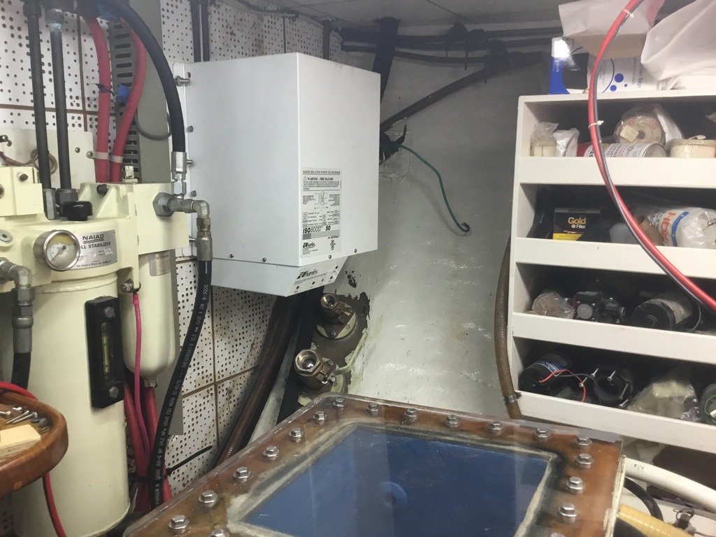
Charles 30 Amp Isolation Transformer

The friendliest place on the web for anyone who enjoys boating.
If you have answers, please help by responding to the unanswered posts.

JDCAVE

Guru
Joined
Apr 3, 2011
Messages
2,902
Location
Canada
Vessel Name
Phoenix Hunter
Vessel Make
Kadey Krogen 42 (1985)
I have purchased and am preparing to install a Charles 30 Amp Isolation Transformer (93ISOG26A) on one of my 30 amp inputs. We only use one of the 30 amp sources as all loads can be accommodated with one. Obviously this will be installed somewhere inside the boat. The input is located behind the washer dryer and there is a tangle of copper plumbing behind there. Also, based on feedback from other KK42 owners, you pretty much have to decommission the stacked washer/dryer unit in order to get back there. I'd like to leave that for another time. The issue:

These units are heavy (70 lbs inside a plywood packing case) but compact. You just can't locate them any old place. I was thinking of locating it where the old freedom inverter charger was located aft of the fuel tank as the backing is sufficiently beefy. I would guess there would be a wire run of some 20 feet to that location and another 20 feet back to the AC panel. Since we are talking about 120 AC, is there any problem with the length of these wire runs?

Second: I assume that the old galvanic isolator should be decommissioned?

Jim
 
I don't know about KK's but I recently installed a galvanic isolator to prevent problems with upgraded marinas in the NW.

I have a bow and stern shore power plug and it was recommended I get an isolator for each...I asked why we couldn't wire it to the selector switch so it would work with both plugs, whichever plug that was selected. All agreed that was a good idea and that was what we did, It works well.

We put it inside the pilothouse near the Plug 1, Plug 2, Gen selector switch.
It did cause electronic problems with compass-autopilot...requiring we relocate the compass sensor.
 
Ken: I already have a galvanic isolator. My question concerns an "Isolation Transformer" that completely isolates the boat from the shore-side power. This especially includes the "ground". As a consequence, I believe the galvanic isolator should be decommissioned.

Jim
 
Sorry..I mis-wrote...should have read isolation Transformer--just installed last July.

Ken
 
I was thinking about doing the same thing - adding an Isolation Transformer and putting it where my Galvonic Isolator is located. I don't see any need for both.
 
With an isolation transformer, you don't need a galvanic isolator. Such a transformer "isolates" the ground from the shore power supply, keeping DC from being transmitted from the shorepower ground to your boat's electrical system.

Your shore power wiring almost certainly is 10 gauge which is what you should use to wire up the new isolator.

David
 
I have purchased and am preparing to install a Charles 30 Amp Isolation Transformer (93ISOG26A) on one of my 30 amp inputs. ...............................

I would guess there would be a wire run of some 20 feet to that location and another 20 feet back to the AC panel. Since we are talking about 120 AC, is there any problem with the length of these wire runs?

OK, so far, nobody has mentioned this:

The ABYC requires overcurrent protection on the incoming wiring within ten feet (measured along the length of the wire) of the inlet. You are planning on adding 40 feet of cable and this far exceeds the ABYC requirement. You will need to install a double pole breaker (breaks the hot and neutral conductors) somewhere within the first ten feet from the inlet.

I would look for a better place for the transformer even if you have to get behind the washer/dryer.
 
I have a bow and stern shore power plug and it was recommended I get an isolator for each. ............

You have to learn who to take recommendations from and who not to. Web forums are the worst for this because anyone can be an expert on the Internet.

The galvanic isolator is not needed with a properly installed isolation transformer.
 
Pretty much every diagram I have seen of isolation transformers use the shore powers ground to ground the transformers case.

Because of that, the isolator (wired between the shore and the transformer) would actually insert a ground fault and the transformers case would not be properly grounded.
 
I don't think so. The Charles installation diagram has the load side ground connected to the case but not the shore power side.

David
 
I installed a 50-amp 120/240-volt ISOBoost last year and it, too, is a beast to move--a 250-lb basketball. As Wes notes, I installed a 50-amp double-pole breaker within 10 feet (actually three ft.) of the shore power inlet. Another breaker On the load side of the transformer provides over-current protection.

This may not help you much, but I installed the ISOBoost on a bulkhead in the ER. I had some stainless steel "staples" made that poke through the bulkhead from the opposite side and distribute the considerable weight better than bolts and washers.


Last edited:
wiring diagram attached

For those interested in this minutia, attached is a page from Charles installation instructions showing the wiring diagram. The shorepower ground is wired to a primary shield (perhaps for RF control) and is indicated to be insulated from case. The secondary (load) ground is tied to the case and the neutral side of the winding. This is allowed (and necessary) as the transformer secondary is the source in NEC terms.

I learned about all of this when I discovered that my Mainship 34T had an open ground. It turns out that when Mainship installed the isolation transformer, they never connected the ground to the case. Anyone who owns a Mainship built in the mid 2000s and has an isolation transformer should check this as others were miswired this way.

David
 

Attachments

  • Charles Isolation Transformer Wiring.pdf
    1.9 MB · Views: 84
Last edited:
I learned about all of this when I discovered that my Mainship 34T had an open ground. It turns out that when Mainship installed the isolation transformer, they never connected the ground to the case. Anyone who owns a Mainship built in the mid 2000s and has an isolation transformer should check this as others were miswired this way.

Please refresh my memory here David. Did they screw up by not connecting the "internal" ground (on the boat-side of the xformer) to the xformer case? Or was the problem on the "shore side" ground (which appears to connect to the xformer shield)?

And what tipped you off that they'd messed the install up?

Dave
 
For those interested in this minutia, attached is a page from Charles installation instructions showing the wiring diagram. The shorepower ground is wired to a primary shield (perhaps for RF control) and is indicated to be insulated from case. The secondary (load) ground is tied to the case and the neutral side of the winding. This is allowed (and necessary) as the transformer secondary is the source in NEC terms.

I learned about all of this when I discovered that my Mainship 34T had an open ground. It turns out that when Mainship installed the isolation transformer, they never connected the ground to the case. Anyone who owns a Mainship built in the mid 2000s and has an isolation transformer should check this as others were miswired this way.

David

It's not "minutia" if you are actually installing one of these transformers. A properly installed isolation transformer is a good thing. An improperly installed isolation transformer may be worse than the original problem that someone is trying to correct.


The attachment makes it all pretty clear.
 
Wire length should be an issue. Just install breakers in the right places, and use heavy enough wire.

My isolation transformers came mounted on rubber isolation mounts, and now I know why. Last year I installed an auto transformer to get 240V service from my 120V inverter service, and when turned on, the auto transformer makes a pretty good humming sound. I heat the isolation transformers too, but not nearly as much. I now have some isolation mounts for the auto transformer to install this summer.
 
Please refresh my memory here David. Did they screw up by not connecting the "internal" ground (on the boat-side of the xformer) to the xformer case? Or was the problem on the "shore side" ground (which appears to connect to the xformer shield)?

And what tipped you off that they'd messed the install up?

Dave

I bought a plug in polarity and ground tester and was somewhat shocked that all outlets had no ground. This was on a two year old boat. I suspected the isolator transformer; it was a standard Mainship item on that boat. So I downloaded the Charles installation instructions, the one I attached a page out of, and noticed that the ground on the boat side, the load side was open, ie not connected.

It was easy to fix, just connect the green wire to the screw on the case which I determined was also appropriately connected to the neutral side of the transformer.

David
 
......... The secondary (load) ground is tied to the case and the neutral side of the winding. This is allowed (and necessary) as the transformer secondary is the source in NEC terms............

This is the key. Just as the neutral and ground are connected together at the electric panel (the "source") in your home, the secondary of the isolation transformer is considered the source on your boat. The neutral and ground are connected together there.

It's surprising and a real shame to find a production boat wired incorrectly. Maybe this was a dealer installed option.
 
.
It's surprising and a real shame to find a production boat wired incorrectly. Maybe this was a dealer installed option.

Nope, the isolator was a standard factory installed item, not even an option. That is why I encourage all Mainship owners of boats built in the mid 2000s to check, well heck everyone- you never know what yahoo wired your boat. The consequences can be deadly.

David
 
Thanks people for your experiences and advice on the installation of an Isolation Transformer (IT). I had figured that the Galvanic Isolator was unnecessary and have confirmed that with Collier's book on corrosion where it is explicitly stated. Wes: Thanks for your points on the GCFI. That is not shown on the installation instructions I had downloaded the from the Charles site but it does make sense. However wouldn't the breaker on the shore power pedestal serve that purpose (hopefully not too dumb a question)? I had also noticed the ground to the case. I presume, though, that the ground on the boat is isolated from the shore ground as that would seem to be the whole purpose of the installation. From the diagram, it would seem that everything, including the generator would go through the IT.

You have to learn who to take recommendations from and who not to. Web forums are the worst for this because anyone can be an expert on the Internet.

That's true for enough, but I did learn something about Ken's particular installation: that a rotary switch could be installed to allow both shore connections to be utilized. Not sure if I will go down that route, but that and where he located his unit and some of the problems he encountered (compass interference issues) are useful to know.

So why ask questions on this forum, since I will be having this professionally installed? A number of reasons. First there are well informed people (Dave, Wes, Peter and others) on this forum who have valuable information to provide and who challenge my own limited knowledge. Second, I get information on what others have done, expert or not on site locations and the like. So when it comes to the actual installation, what the electrician does is obvious, and some time (think $) can potentially be saved as some of the issues have been thought through before hand. Finally, I can be at least somewhat informed so that if the electrician does something I don't understand, at least I will know enough to ask for an explanation.

Thanks all!

Jim
 
Thanks for your points on the GCFI. That is not shown on the installation instructions I had downloaded the from the Charles site but it does make sense. However wouldn't the breaker on the shore power pedestal serve that purpose (hopefully not too dumb a question)?

The reason for a breaker on your boat shortly after the inlet is in case the shore power breaker is larger than yours. This happens when you use adapter cords on the dock side of things. For example, a splitter to get 30A off a 50A dock outlet. The power from the dock to the breaker on your boat is limited to 50A, even though you could be (and probably are) using only a 30A cord, and your boat it wired for 30A. The breaker on your boat protects everything if it goes over 30A. The only exposure is a wiring problem between the dock and your breaker.

I had also noticed the ground to the case. I presume, though, that the ground on the boat is isolated from the shore ground as that would seem to be the whole purpose of the installation.

The isolation transformer has two separate grounds and they are not connected together. The charles document shows this, but it's not super clear. The shore-side ground connects to an internal shield inside the transformer windings. The boat's ground connects to the transformer case, and is bonded to the neutral somewhere on the boat.
 
Jim:

I agree with your approach as you seem to have the ability to sort out the wheat from the chaff in all of these replies. Also it is good to be knowledgeable even when a "professional" is doing the work, to keep him on track.

I am reminded of the case when a friend hired a commercial marine electrician to install an inverter/charger on his boat. The electrician couldn't understand what I was telling my friend. The electrician and I talked directly and I told him that the inverter/charger had an internal transfer switch so wire the incoming shore power to that side of the switch and then to the main electrical panel. He had a "aha" moment as he had never dealt with an internal transfer switch in his commercial work.

David
 
Nope, the isolator was a standard factory installed item, not even an option. That is why I encourage all Mainship owners of boats built in the mid 2000s to check, well heck everyone- you never know what yahoo wired your boat. The consequences can be deadly.

David

My concern was the lack of connecting the neutral and ground on the boat side of the transformer. A factory that doesn't understand the installation of products it installs is suspect in many ways.

A galvanic isolator passes AC just fine. It only blocks very low voltage DC current. It's not needed with an isolation transformer but it does no harm.
 
The boat's ground connects to the transformer case, and is bonded to the neutral somewhere on the boat.

Um, not "somewhere" - at the transformer case and ONLY at that point. You are establishing a "new" ground point which is only done at the "service entrance" and this is its equivalent on the boat.

The Charles manual illustrates this but doesn't particularly explain it.
 
Um, not "somewhere" - at the transformer case and ONLY at that point. You are establishing a "new" ground point which is only done at the "service entrance" and this is its equivalent on the boat.

The Charles manual illustrates this but doesn't particularly explain it.

I agree that's the preferred location. But a single bonding point is the most important thing, not it's exact location.

It's quite common to have ground and neutral bus bars located elsewhere, and to bond at that location. I don't think bonding right at the source is that important electrically, but it is indeed the convention and helps someone know where to look to find the bonding point.
I'm sorry, but you are confusing several things here. Bonding is a DC-wiring concept - and to keep swimmers from being electrocuted it is indeed important to connect that DC ground to the AC ground somewhere aboard, like you described at the panels or bus bars. But that is different from the principle of connecting the "grounded" (white) and "grounding" (green) wires together at one - and only one - point, which is the "source" of the power. Sometimes that "source" is ashore, sometimes that is an on-board generator. The issue is, if you break that shore connection with an isolation transformer, you need to create a new ground point AT THE SOURCE, which is...the isolation transformer.

To quote Steve D'Antonio:
"All voltage produced by the isolation transformer seeks a return to its origin, not just any ground. The importance of this feature cannot be overemphasized. Shorepower voltage, once it passes through the isolation transformer, will return only to that isolation transformer, through either the white neutral conductor or the green safety grounding conductor, whether by design or fault."
 
Believe me, I completely understand it. Even Steve will vouch for that.

"Bonding" is nothing more than connecting two circuits together. Tying your DC negative to all your thruhulls is Bonding, and commonly referred to as such. But tying the neutral and ground together is also commonly referred to as Bonding. But we can call it something different if you prefer. And I agree with you that it gets done in different locations depending on the situation, in particular what the power source is.

I think we are in near total agreement, but getting tangled up in language. I apologize if I have been sloppy in that respect.

The only point I was trying to make is that when the neutral and ground are to be tied together onboard, as when using an isolation transformer, the connection point doesn't HAVE to be physically at the transformer. It can be elsewhere on the boat, for example in an electrical cabinet or panel where there might be ground and neutral bus bars. My boat is an example of exactly that.
 
Thanks again everyone. The Charles installation manual suggests two methods for installation, with Method 1 being the most common. Method 1, a circuit breaker is employed on the vessel between the shore power and the IT. Method 2, a GFI breaker is used on the vessel between the shore power and the IT. On Method 1 the ground on the boat seems to be connected with the shore power, while on Method 2 there is no connection between the boat ground and shore ground.

It would seem to me that Method 2 is preferable for the purposes of protection against Galvanic corrosion. Is one method preferable above another, or are they equivalent for corrosion control and the bonding system? Would a would the GFI be more sensitive to moisture?


http://www.charlesindustries.com/marine_manual/ISOG26-1_pr3.PDF

Jim
 
Last edited:
Thanks again everyone. The Charles installation manual suggests two methods for installation, with Method 1 being the most common. Method 1, a circuit breaker is employed on the vessel between the shore power and the IT. Method 2, a GFI breaker is used on the vessel between the shore power and the IT. On Method 1 the ground on the boat seems to be connected with the shore power, while on Method 2 there is no connection between the boat ground and shore ground.

It would seem to me that Method 2 is preferable for the purposes of protection against Galvanic corrosion. Is one method preferable above another, or are they equivalent for corrosion control and the bonding system? Would a would the GFI be more sensitive to moisture?


http://www.charlesindustries.com/marine_manual/ISOG26-1_pr3.PDF

Jim


In both methods the boats ground and the shore ground are separate. This is because the shield connection and the case ground in the transformer are not connected. So in both cases you get full isolation of grounds between the boat and shore.

I would use method 1. I think you get a little more protection by carrying the shore ground all the way to the transformer.
 
Thanks Peter: Apparently Method 1 is the more usual installation. So perhaps I'm a little dense here. To confirm: In Method 1, the ground and the boats bonding system ARE NOT connected with the shore ground? Only the IT shield?

That's why we hire a professional!

Jim
 

Latest posts

Back
Top Bottom