Int. P Shaft brng & Thrust

The friendliest place on the web for anyone who enjoys boating.
If you have answers, please help by responding to the unanswered posts.
Joined
Oct 31, 2007
Messages
18,745
Location
USA
Vessel Name
Willy
Vessel Make
Willard Nomad 30'
I asked for a new intermediate bering to be installed. The yard tried to remove the old bearing by cutting it out. But they cut into the shaft. They then finished the job of cutting it out. They made me a new shaft and finished the installation. But the guys put a locking collar on the shaft just behind the inner race of the ball bearing thus turning it into a thrust bearing.

It's my understanding that the propeller shaft needs to move back and forth as the power pulses push like a jackhammer every time a cylinder fires. Also from my understanding engine mounts allow for fore and aft movement as part of their design.

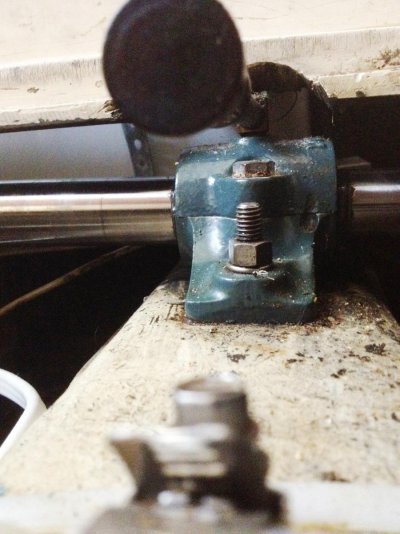
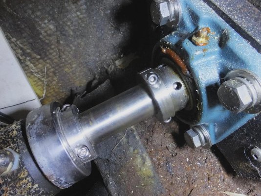
In the first pic the collar is tight on the shaft as the yard birds installed it. The second pic is where I have it now .. against the PSS bearing. In the past I've had problems w the PSS bearing moving fwd far enough to allow a great deal of water to enter the boat. Since the collar was there I put it to work.


IMO the yard should have omitted the locking collar against the int. brng entirely. The presence of the collar against the inner race of the brng turns the brng into a thrust brng and does not allow the shaft to move fwd and aft. This in turn transfers the fore and aft vibration from the shaft into the boat hull through the int shaft brng mounting.

After a run lasting hours I discovered the int. brng was quite hot. Hot enough so I was only able to touch it for 1 second. I pumped a little more grease into the brng. Did little if any good. I noticed after a test run later at the dock that the collar had been slipping on the fore and aft face of both the int. brng and the collar .. taking the thrust of the shaft. So probably the collar was acting like a dry steel to steel thrust brng Bad.

That's when I moved the collar aft against the PSS. Haven't been out w the boat since that move. I hope that now the shaft will move freely fore and aft and allow the fore and aft movement to be transferred to the engine mounts where it belongs IMO. And that the whole arrangement runs nice and cool.

My question is have I misunderstood the way the intermediate shaft bearing is designed to work or what? If the shaft slides freely on the inner race of the int shaft brng the big ball brng becomes a plain brng. The ball brng is low drag so w a loose fitting shaft to inner race there would be either a lot of wear on the shaft or the vibration is sent to the boat hull via the brng mount.

How is this supposed to work?
 

Attachments

  • DSCF2381 copy.jpg
    DSCF2381 copy.jpg
    173.7 KB · Views: 69
  • DSCF2382 copy.jpg
    DSCF2382 copy.jpg
    123.1 KB · Views: 67
Last edited:
Eric,
The intermediate bearings are supposed to be steading bearings.
Some bearings have a coller that will lock the shaft to the race to
absorb a percentage of the load as thrust.
The coller you show does not look like that type of coller to me.
If it is running steel to steel as you think and producing the amount
of heat you indicate I think it is set up wrong.:eek:

Also heat is in this case wasted horsepower,you could use a smaller
engine.:rofl:

Ted
 
Eric,

I studied the shaft and intermediate bearings used in Willard and Fales boats a couple of years ago when I faced a shaft vibration issue in Boomarang. It appears that Willard in many of the Vegas used the shaft/bearing design you have. Those Dodge flange-mount setscrew ball bearings are designed to be locked to the shaft precisely so that they cannot slide and wear. The inner bore of the bearing race and the shaft are not bearing surfaces. By locking the bearing to the shaft, effectively the intermediate bearings become thrust bearings. This obviously works, as there seem to be many Willards with this arrangement. I imagine the pulses you describe are largely absorbed by the mass of the flywheel to the point where they are negligible.

Fales chose Dodge babbitt sleeve bearings that support the shaft while allowing the shaft to move freely fore and aft. In this way, the engine thrust is transmitted to the hull structure via the engine mounts. The intermediate bearings only stabilize the un-supported shaft and eliminate whipping. With Yanmar power and their very flexible engine mounts, this is the only solution that makes any sense. This was also the arrangement for the original Perkins 4-107 as well. Boomarang's shaft moves about 3/16" (3/8" total) fore and aft with fresh engine mounts.

BTW, PSS now recommend locking collars on their shaft seal installations and sell them directly.
 

Attachments

  • IMG_0705.jpg
    IMG_0705.jpg
    137.5 KB · Views: 61
Ted I would think it would "absorb" all the thrust or none of it.
In this case the inner race has a threaded hole whereas a set screw could be installed. Of course these bearings are off the shelf units for whatever use they can be fit. Not really intended for marine use. Just like all "marine" engines (new).

I'm think'in I'm going to need to unbolt the flange from the trans and slide it aft about 2" to clean and neversieze or otherwise lube the shaft. Otherwise it will corrode itself to the inner race and I'll be right back to where I started.

I wish I had a lignamvita "steadying bearing".
 
Eric,
When I used those bearings they had a rating for how much they could carry as
a steady bearing.
The locking coller was bored eccentric and fitted over the "spigot" that protruded
from the bearing. Slide it on, twist to "jam" the shaft and tighten the set screw.
The thrust load was rated as percentage of the bearing rating.
Your coller does'nt appear to fit over the "bearing spigot" but only rides against
it.

You could use a teflon type bearing instead of a lignamvita bearing. I did that
on a rudder pintle bearing, worked well.
I think there are even better "plastics" now.

Ted
 
LarryM,
Well this is'nt what I wanted to know.
In order to use the threaded hole and lock the inner race to the shaft I'd need to locate the exact spot and put a serious dimple on the shaft. Deep enough to hold about 1000lbs loaded in sheer. And I do'nt want that vibration in my boat either.

I could of course replace the bearing I have now w the babbitt bering that the Fales has but w the haulout ect that would be a boat buck. If I had access to the other side of the bearing I could install one or two "collars" (as seen in my pics) on both sides of the inner race of the bearing thus locking it fore and aft. Probably could do that if I cut out some of the floor ahead of the bearing. And of course I don't know what's down there. In this case it appears to me that Fales knew more about what they were doing than Willard. Just my opinion though.
With the babbitt bearing one would need to grease it quite regularly I suppose. And to pic up the grease droppings I'd need to cut out the floor anyway.

Again I sure wish I had a Lignamvita bearing. For those that are'nt famillar w Lignamvita it's a very dense and heavy wood. It sinks in water. Most of the old salmon trollers up north had Lignamvita stern bearings .. in lieu of the modern brass sleeve with fluted rubber inside.

Thanks again for your excellent input Larry.
 
That bearing is not appropriate to the application. Neither the lock collar nor the setscrew can hold the prop thrust load. Engine and gear are on flexible mounts so thrust will cause fwd/aft displacement of the shaft. Shaft will move in that bearing as a result. And the rather trivial restraints via collar or setscrew are not going to hold it.

I wonder why the bearing is there at all. How long is the shaft and what is the fwd/aft spacing of the rigid supports? And what diameter shaft and speed? Those are the criteria for the shaft whipping calc, which is why intermediate bearings get spec'd.

Without knowing all the details, I'd be tempted to recommend letting the bearing ride loose on the shaft, and hopefully inner race will spin with it and not act as a journal bearing. Or maybe put a split piece of hose on shaft and inner race and hose clamp it togther. That way you are assured race will spin with shaft yet thrust load will be taken by gear.

I've designed a bunch of shaft lines and would never use that bearing style unless it was the sole thrust carrying device, and shaft restrained accordingly.
 
Ted,
If I was to put a "locking collar" on as you describe I could lock the shaft w the collars as in my pics w the same result. Except there would be a very small amount of radial "slop" depending on the fit of inner race to shaft.

Derlin would perhaps be a suitable material. On several of my ultralights derlin was used for wheel bearings. Brief loads only though.
I wonder if I could get a babbitt bearing w the same configuration and bolt pattern? Probably can. But that's still a haulout and considerable work.
Oh now I see I'd have to drill a dimple on the shaft and install a set screw to use the collars. Larry's probably right the resulting vibration from locking the bearing probably would'nt be much. I'd be pretty unhappy if it was though. I may have the smoothest 30' Willard in existence and I'd sure like to keep it that way.
And if I run the boat w/o fixing this I'll probably ruin the shaft. ????
 
Ski,
Thanks so very much. That's what I thought ... that it was an "inappropriate" arrangement.

The rubber hose solution sounds a little flimsy but if it works I'd be OK and would save the shaft for a better fix later on. But if it worked w a split hose it should work even better w a hose not split. Such a hose could be installed at the next haulout. When I go to sell the boat I wonder what the surveyors would think? HaHa

The shaft is 1 1/4" , wot rpm is 3000 and a 2.57-1 gear is used. About 1200rpm. It's about 5' aft to the cutlass and about 4' fwd to the trans output.
 
LarryM,
With the babbitt bearing one would need to grease it quite regularly I suppose. And to pic up the grease droppings I'd need to cut out the floor anyway.

Eric,

You spotted that right away now didn't you:rofl:

You are right, they require lube frequently and are messy. I actually cut out some diapers to lay under/around them to keep the grease from dripping into the bilge. Based upon records from the prior owner, the last bearings (2) lasted about 500 hours. Thankfully, they are easy to change, and are about $95 each.

To fit a pillow block style bearing, you would need to modify your existing bearing support to include a shelf for support. Alignment and positioning of the bearing would be pretty important too.

How well did the original flange bearing perform? It seems to have lasted a while, or have you replaced it before? Depending upon the design of the bearing, some do have some 'thrust' capability. With only 40hp or so, I believe the thrust is well under 1,000# max.

Dodge, Moline, Sealmaster and other manufacturers make a double tapered roller bearing in a 4-bolt flange configuration. The Dodge E-Series is rated at over 1,000# thrust in the 1-1/4" size. Note that they have 4 set screws to lock the shaft to the inner race. These would provide a much more substantial solution that would not require any modifications to your existing setup.

Note - these are not self-aligning bearings, they would need to be shimmed to align perfectly with the shaft when installed.

$_57.JPG


$_57.JPG
 
Last edited:
Eric,
When I used those bearings they had a rating for how much they could carry as
a steady bearing.
The locking coller was bored eccentric and fitted over the "spigot" that protruded
from the bearing. Slide it on, twist to "jam" the shaft and tighten the set screw.
The thrust load was rated as percentage of the bearing rating.
Your coller does'nt appear to fit over the "bearing spigot" but only rides against
it.

You could use a teflon type bearing instead of a lignamvita bearing. I did that
on a rudder pintle bearing, worked well.
I think there are even better "plastics" now.

Ted

Vesconite is a plastic bearing.
https://www.vesconite.com/
I ordered prop shaft bushes from them in 2006 and still they are working ok.
 
Movement of a shaft is decided by the transmission installed.

Some move their flange shifting , some don't.

I would go with the bearing as a shaft centering bearing , and let the tranny take the thrust load as it was designed to do.

There are better grade shaft bearings that can be R&R without disturbing the shaft.
 
Thanks all very much,
I now have a good solution to the problem.
I really liked Ski's idea of using a split hose clamped to the inner race and the shaft. Was concerned about the hose sliping off in reverse.
On the end of the inner race that sticks out I'd clamp a 1" split tube of strong plastic or metal. A half shell. And I'd make a half shell of SS with an ID to fit the shaft. Near the fwd end I'd have a little rod about 1/8" dia and 1/4" long welded to the shell sticking up about 1/4". Up enough to engage the half shell clamped to the inner race.
With this arrangement the shaft is free to move fore and aft. The outer race will follow the inner race except for the 160 degrees of the open half shell on the inner race.
Sorry it's getting kinda wordy.
But I think it will totally solve the problem. The shaft to inner race movement allowed may keep the shaft from corroding and sticking to the inner race. Every time I shift it will need to move 160 degrees .. inner race to shaft. The only thing I'm a little worried about is the half shell coming off the inner race edge.

FF interesting about the brngs that can be R&Red w the shaft in place.

717 Visconite ... That's great. And you used it as a shaft bushing. Lubed I assume.

Larry I really like that bearing in the pics but I'm set on allowing the shaft to move fore and aft. Also aligning it would be a big deal ... TOO MUCKING FUCH.

SO I've got a little fabricating to do. I'll do a followup later.

The vesconite is lubed by the sea water.
It goes into the strut. Been ok. I installed myself.
Had struts off boat, and put the vesconite bushings into the freezer. Then pressed them in.

I called South Africa and talked to them and they custom machined and shipped by airmail.
They were cheap like $25 for two 6 inch long for 1 3/8 inch shafts.

If I replace them, maybe I can use a pipe and large threaded rod.
On my 2014 haulout, there was no wear, they had the same clearance as from 2005.

But one thing, a thin crab pot line had wrapped round the shaft and dug into the vesconite next to the prop. So next haulout I am going to replace them.
 
Last edited:

Latest posts

Back
Top Bottom