110v ground connected to 12v neg

The friendliest place on the web for anyone who enjoys boating.
If you have answers, please help by responding to the unanswered posts.

seattleboatguy

Senior Member
Joined
Nov 2, 2013
Messages
327
Location
USA
Vessel Name
Slow Bells
Vessel Make
Marine Trader 38
I've been spending a little time each day with a multi-meter, trying to understand the rats nest of wiring on my boat. Like many old boats, it's a mess of epic proportions, but I'm slowly figuring out what runs where. One of the things that seems strange to me is that I'm seeing electrical continuity between the shore power ground wire and many of the 12 volt negative wires. Is that okay, and if so, what is the theory behind connecting these 2 systems?
 
Per ABYC E-11 "DC and AC electrical systems on boats," The Shore Power green grounding conductor is required to be tied to the 11.17.1.4.3 the engine negative terminal or its bus.
 
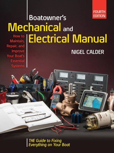
This is OK if done correctly! - a great reference is Boatowner's Mechanical & Electrical Manual by Nigel Calder.
I'm assuming when you say "shore power ground" you actually mean the onboard 120V AC.

To be correct the connection between the two (AC & DC sytems) is by tieing their respective & separate ground bus bars together - not by connecting an AC appliance ground to a DC negative wire.

There are also some important Do's & Don'ts re: AC ground aboard vs to shore - don't know if you have an isolation transformer / isolator but the ref: book above covers both in detail... highly recommend it.
 

Attachments

  • Calder - Mech & Elec Manual 4th Ed.jpg
    Calder - Mech & Elec Manual 4th Ed.jpg
    99.6 KB · Views: 85
I've been spending a little time each day with a multi-meter, trying to understand the rats nest of wiring on my boat. Like many old boats, it's a mess of epic proportions, but I'm slowly figuring out what runs where. One of the things that seems strange to me is that I'm seeing electrical continuity between the shore power ground wire and many of the 12 volt negative wires. Is that okay, and if so, what is the theory behind connecting these 2 systems?

I think the theory is if you don't you would energize your 12V system to 120V if there is a short AC to DC, which would make for bad times for anyone touching almost anything grounded on 12V side - whereas if they are bonded, a short will (hopefully) trip a breaker (or GFI)
 
......... One of the things that seems strange to me is that I'm seeing electrical continuity between the shore power ground wire and many of the 12 volt negative wires. ...

How could it be "many" of the 12 volt negative wires?

If you don't observe continuity between all of the 12 volt negative wires, you either have a problem or you aren't using your meter correctly.


My suggestion is to put down the meter and pick up a good boat electrical book. Study the book until you think you understand electricity, then get out your meter and see if what you think you find matches what you think you should find.
 
Last edited:
How could it be "many" of the 12 volt negative wires?
That's easy to answer. There are several "groups" of 12v neg terminals, created by electrically joining individual terminals using a piece of metal. Some groups have the continuity with the 120v ground. Some don't. And sorry, there is no way I'm putting down my multi-meter. It is the best tool I have to understand how my boat is currently wired. You can't get that from a book. Once I understand how the system is currently wired, THEN the books will be used to help me improve what's there.
 
That's easy to answer. There are several "groups" of 12v neg terminals, created by electrically joining individual terminals using a piece of metal. Some groups have the continuity with the 120v ground. Some don't. And sorry, there is no way I'm putting down my multi-meter. It is the best tool I have to understand how my boat is currently wired. You can't get that from a book. Once I understand how the system is currently wired, THEN the books will be used to help me improve what's there.

All 12v negatives should have continuity to engine GND. meaning all should tie eventually to a common D.C. ground. So something is pretty screwy if groups of D.C. Grounds connect together but not to each other. Or possibly some aren't actually D.C. Grounds or some have been disconnected and are no longer used.

Ken
Hi Ken. Most all the -12v wires tie into the batteries. It's just that some groups have 120v grounds scattered in there. You are correct that some of the wires which are connected to a terminal strip at one end simply dead-end at the other end. I found 2 of those yesterday. To me, the more alarming discovery was finding +12v wires and hot 110v wires on the same terminal strip. I like the idea of having separate terminal strips for the different voltages. Once I understand what's there now, it will be time to get out the books and try to improve things.
 
Hi Ken. Most all the -12v wires tie into the batteries. It's just that some groups have 120v grounds scattered in there. You are correct that some of the wires which are connected to a terminal strip at one end simply dead-end at the other end. I found 2 of those yesterday. To me, the more alarming discovery was finding +12v wires and hot 110v wires on the same terminal strip. I like the idea of having separate terminal strips for the different voltages. Once I understand what's there now, it will be time to get out the books and try to improve things.

Dead ends are not totally uncommon with older boats as things get rewired through the years. But unless you have some totally isolated 12V runs (don't know where the power would be coming from/going to) then yes, all 12V negatives should have continuity back to the engines. This is a bit simplistic but - Basic electronics - no current can flow without a complete circuit - from 12+ to the device(usually through a switch and always through a fuse or breaker), then from the device back to 12V negative. Usually the 12V negatives are combined on a large bus bar. One can have multiple 12V negative bus bars, but any bus bars in turn need to be tied together with heavy gauge wire, then by heavy gauge wire back to the battery(ies). No 120V grounds should go to the 12V neg buss bars - they should have their own bus bar, but there should be ONE connection between the 120V GROUND buss bar and the 12V grounds.

It sounds like you're on the right track. Identify those 120 grounds and get them all onto their own bus bar. Then do the same for the 12V grounds.

I agree with you that its not the best idea to use part of a terminal strip for 120V lines and another part for 12V. Too easy to make a dangerous connection by accident.

Ken
 
All 12v negatives should have continuity to engine GND. meaning all should tie eventually to a common D.C. ground. So something is pretty screwy if groups of D.C. Grounds connect together but not to each other. Or possibly some aren't actually D.C. Grounds or some have been disconnected and are no longer used.

Ken

That's the point I was trying to make.
 
................To me, the more alarming discovery was finding +12v wires and hot 110v wires on the same terminal strip.................

That would make your 12 volt DC system "hot". 120 volts hot.

I think you are misinterpreting things here and I suggest hiring a qualified marine electrician to inspect and correct your boat's wiring.
 
That would make your 12 volt DC system "hot". 120 volts hot.

I think you are misinterpreting things here and I suggest hiring a qualified marine electrician to inspect and correct your boat's wiring.

You misread his post. He doesn't like having 120 and 12 volts on the same terminal strip. He didn't say they were tied together.
 
That would make your 12 volt DC system "hot". 120 volts hot.

I think you are misinterpreting things here and I suggest hiring a qualified marine electrician to inspect and correct your boat's wiring.
You did not interprete my explanation as I intended. My 12v DC system is not "hot". Let me try again. Each pair of screws on a terminal strip are electrically connected. In addition, you can add a long piece of metal to the terminal strip to tie several pairs together. On my terminal strip that has both +12v and hot 110 connections, none of the adjacent terminal pairs are connected. They are electrically isolated from one another, but they are dangerously close to one another. I hope that makes more sense.
 
In my boat the original build had separate strips for all of the potentials (120H,120N,120G,+12,gnd) but over the years many different hands had their try at completely screwing it all up.

The one book referenced earlier can give you a pretty good
head start at knowing what should have been done rather than what was done.
I have a suspicion that a similar thing happened on my boat over the years. I'll give that referenced book a good study before I change anything.
 
Back
Top Bottom