You are using an out of date browser. It may not display this or other websites correctly.
You should upgrade or use an alternative browser.
You should upgrade or use an alternative browser.
Show us your ER
- Thread starter FlyWright
- Start date
The friendliest place on the web for anyone who enjoys boating.
If you have answers, please help by responding to the unanswered posts.
If you have answers, please help by responding to the unanswered posts.
OP
OP
- Joined
- Apr 15, 2008
- Messages
- 13,731
- Location
- California Delta
- Vessel Name
- FlyWright
- Vessel Make
- 1977 Marshall Californian 34 LRC
Carey wrote:
-- Edited by Carey on Sunday 3rd of April 2011 08:30:47 PM
Carey must be at a loss for words!
Very nice work, Bill. I wish I could do woodwork like that!
I see a lower helm, but no wheel.* Is it removable?
*
Enola B
Veteran Member
- Joined
- Nov 29, 2009
- Messages
- 29
Wheel is off for it's own protection. Both lower and upper helm have nice varnished teak wheels so keeping them safe while work is in progress.
Sailor of Fortune
Guru
Looking good Bill.
Phil Fill
Guru
- Joined
- Oct 11, 2007
- Messages
- 2,919
- Location
- US
- Vessel Name
- Eagle
- Vessel Make
- Roughwater 58 pilot house
The engine room would be a lot less cluttered and more room if there was not those two big green*metal thingies running smack dab in the middle of the room.* The*hight is about 6 ft, there is a work area between the to big metal things, and there is a walk way on each side for easy access.* But after*seeing Deflin purdy engine room its need re painting and carpeting.* But I do vacuum and dust once a month.
*
-- Edited by Phil Fill on Monday 4th of April 2011 02:40:39 PM
*
-- Edited by Phil Fill on Monday 4th of April 2011 02:40:39 PM
Attachments
markpierce
Master and Commander
- Joined
- Sep 25, 2010
- Messages
- 12,557
- Location
- USA
- Vessel Name
- Carquinez Coot
- Vessel Make
- penultimate Seahorse Marine Coot hull #6
*But even when it is well-organized, it still drives me crazy.* I hate electrical.superdiver wrote:
That electrical makes me SICK,
WITH ENVY!
*
- Joined
- Jun 25, 2008
- Messages
- 10,104
- Location
- Australia
- Vessel Name
- Now boatless - sold 6/2018
- Vessel Make
- Had a Clipper (CHB) 34
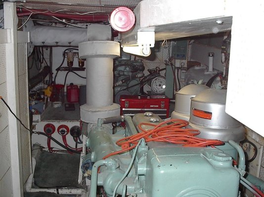
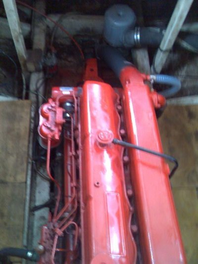
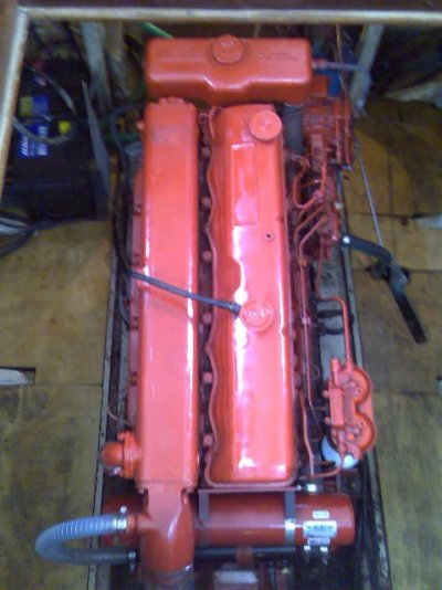
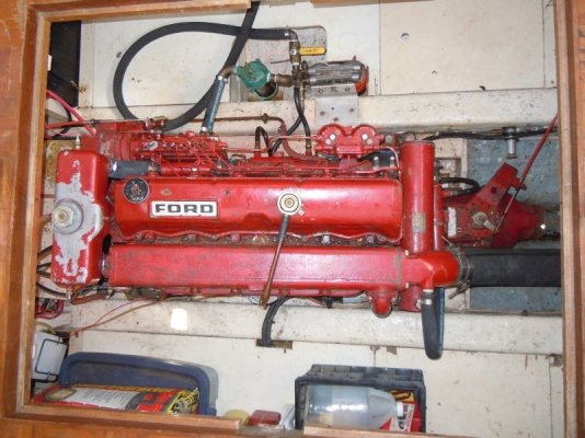
Well, I can't show an engine room, because there is none - room that is - only enough to crawl round all sides and one can stand up through the floor aperture in certain places, so not too bad to work on, but can't get far enough away to get a photo except from above.* So here she is after new heat exchanger and exhaust injection knuckle and oil coolers, all nice new and red, shamed me into degreasing and painting the rest of the engine to match.* Went out for the first time in 4 months (due to delays getting parts etc) and she ran like a dream - all good again.
As an aside - nice to see not all ERs are as pristine as...well..the eat your breakfast off variety - made me feel a bit less infra....
*
-- Edited by Peter B on Tuesday 5th of April 2011 03:23:34 AM
As an aside - nice to see not all ERs are as pristine as...well..the eat your breakfast off variety - made me feel a bit less infra....
*
-- Edited by Peter B on Tuesday 5th of April 2011 03:23:34 AM
Attachments
shipshape
Senior Member
- Joined
- May 23, 2010
- Messages
- 117
- Location
- Australia
- Vessel Name
- Eliza 1
- Vessel Make
- Halvorsen 42 Pilothouse
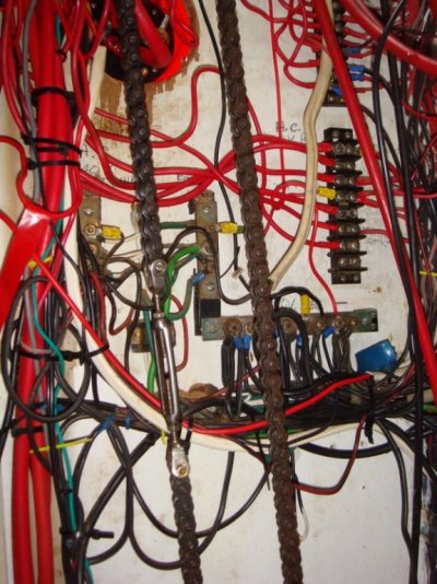
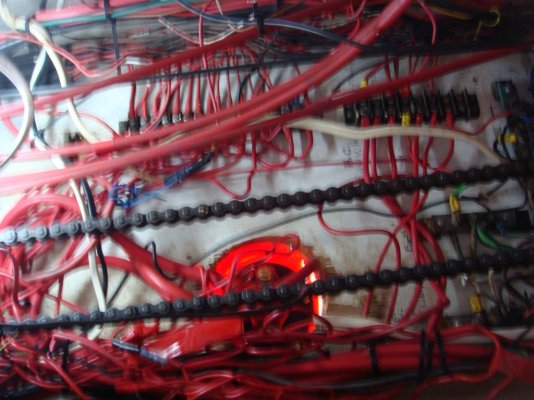
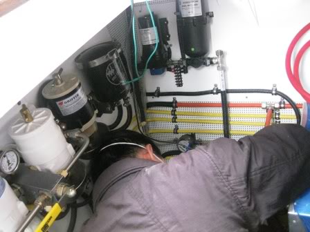
Bill, That electrical looks fantastic .... that's my next step .... nice ER ! ... looks like you also spend a lot of time .....
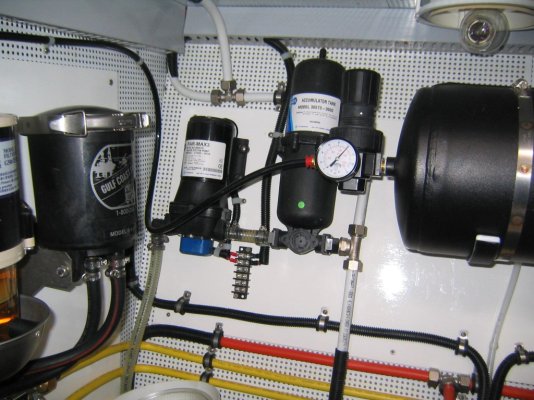
My electrical attached .... looks similar to yours ... with a bit of imagination
 *....
*....
-- Edited by shipshape on Tuesday 5th of April 2011 04:00:47 AM
My electrical attached .... looks similar to yours ... with a bit of imagination
-- Edited by shipshape on Tuesday 5th of April 2011 04:00:47 AM
Attachments

OP
OP
- Joined
- Apr 15, 2008
- Messages
- 13,731
- Location
- California Delta
- Vessel Name
- FlyWright
- Vessel Make
- 1977 Marshall Californian 34 LRC
We could start a new thread on electrical panels, but I'd be too embarrassed to post. Erik's looks great compared to mine.
Nomad Willy
Guru
Phil,**** So nice and I love almost everything about DDs and it looks like you may have a DD gen too. I see those air cleaners and that stack*** ....that baby must PUMP AIR.
*Erik,**** My wiring is a bit of a mess too but I have'nt got the balls to post a picture of it. That's a real Rand McNally boat you've got there. Seeing what you've done w other parts of the boat I've got high hopes.
Peter B,**** Every once in a while I see a pic of a Lehman that makes me admire them. Yours looks a bit like a Buick straight eight*** ...like them even more than the Detroit's.
markpierce
Master and Commander
- Joined
- Sep 25, 2010
- Messages
- 12,557
- Location
- USA
- Vessel Name
- Carquinez Coot
- Vessel Make
- penultimate Seahorse Marine Coot hull #6
From what little I've seen to date, it appears to be neat and organized.* S'pose that's an advantage of a new boat.

JohnP
Guru
- Joined
- Dec 13, 2009
- Messages
- 1,361
- Location
- USA
- Vessel Name
- V E N T U R E
- Vessel Make
- 1996 36' Island Gypsy Classic
********* Mark,* One of the many advantages for sure!* She looks ready to ship any timetable for shipping?*markpierce wrote:
From what little I've seen to date, it appears to be neat and organized.* S'pose that's an advantage of a new boat.
JohnP
*
markpierce
Master and Commander
- Joined
- Sep 25, 2010
- Messages
- 12,557
- Location
- USA
- Vessel Name
- Carquinez Coot
- Vessel Make
- penultimate Seahorse Marine Coot hull #6
Target shipping date for the Coot is April 18.
BaltimoreLurker
Curmudgeon
- Joined
- Oct 8, 2007
- Messages
- 2,775
- Location
- USA
- Vessel Name
- Moon Dance
- Vessel Make
- 1974 34' Marine Trader Sedan

- Joined
- Jun 25, 2008
- Messages
- 10,104
- Location
- Australia
- Vessel Name
- Now boatless - sold 6/2018
- Vessel Make
- Had a Clipper (CHB) 34
Goodonya Darrell. Brave man putting it up there like it is. Actually looks pretty honest really.
Erik, to be honest I actually forgot to take before pictures - truly - it was sort of like "there thats finished....oh bugger, forgot to take a before pic - damn". However, if you look at Darrell's, aka BaltimoreLurker's pics, and imagine even less paint on the header tank and rocker cover and exhaust manifold, and the rest about the same - that would be about it - the before pics I mean.
Erik, to be honest I actually forgot to take before pictures - truly - it was sort of like "there thats finished....oh bugger, forgot to take a before pic - damn". However, if you look at Darrell's, aka BaltimoreLurker's pics, and imagine even less paint on the header tank and rocker cover and exhaust manifold, and the rest about the same - that would be about it - the before pics I mean.
BaltimoreLurker
Curmudgeon
- Joined
- Oct 8, 2007
- Messages
- 2,775
- Location
- USA
- Vessel Name
- Moon Dance
- Vessel Make
- 1974 34' Marine Trader Sedan
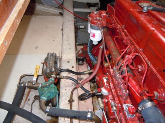
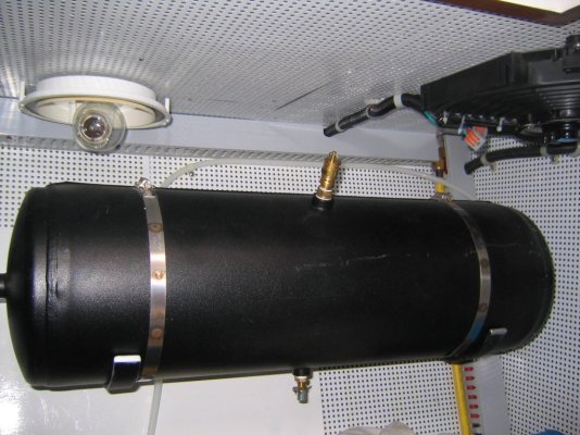
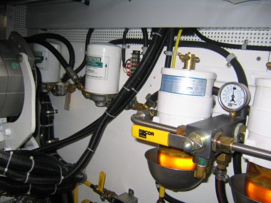
Thanks, Peter!* I am years from addressing the cosmetic issues on my boat.* But, I do have most of the crud out of the engine room.* And, you'll notice a couple nice upgrades in the pics; the dual, remote oil filters (by the PO) , the spin on fuel filters (by me, because the CAV's looked almost original), the coolant recovery tank from American Diesel,* and one you can't quite see - the air-filter fix as described by a MTOA member years ago, and the extra valve on the raw water intake that is very handy for ingesting anti-freeze when winterizing and could be used to assist dewatering in a last ditch effort to remain afloat.
*
*
ralphyost
Senior Member
Baltimore Lurker
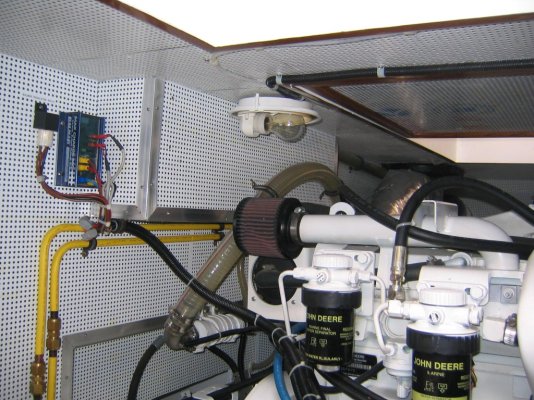
I see you have the copper pipe from the air filter to the valve cover beather.
Suggest you get rid of the copper pip and replace it with all hose.
I know of one Lehman 120 owner who had this setup, and the copper pipe came loose, fell on the POS terminal of his starter, then shorted to the engine block. NOT GOOD !
I changed mine to all hose after hearing about this.
R.
jleonard
Guru
- Joined
- Jun 25, 2008
- Messages
- 5,063
*I have the copper also.... I'll be changing it now. Thanks.ralphyost wrote:
I see you have the copper pipe from the air filter to the valve cover beather.
Suggest you get rid of the copper pip and replace it with all hose.
I know of one Lehman 120 owner who had this setup, and the copper pipe came loose, fell on the POS terminal of his starter, then shorted to the engine block. NOT GOOD !
I changed mine to all hose after hearing about this.
R.
*
ralphyost
Senior Member
Yeah the guy who had this Cu pipe short out on him saw a picture of my engine room just like I saw this one. Then he wrote me an email and PLEADED with me to change it ! His experience was so awful and costly !
R.
R.
BaltimoreLurker
Curmudgeon
- Joined
- Oct 8, 2007
- Messages
- 2,775
- Location
- USA
- Vessel Name
- Moon Dance
- Vessel Make
- 1974 34' Marine Trader Sedan
*ralphyost wrote:
I see you have the copper pipe from the air filter to the valve cover beather.
Suggest you get rid of the copper pip and replace it with all hose.
* Yikes!* Good call!* That pipe does want to fall off all the time.* Thanks for the heads-up.
Fotoman
Guru
- Joined
- Nov 12, 2009
- Messages
- 649
Since we are talking about that pipe. What is it for? It looks like such an akward arrangement to me.
- Joined
- Jun 25, 2008
- Messages
- 10,104
- Location
- Australia
- Vessel Name
- Now boatless - sold 6/2018
- Vessel Make
- Had a Clipper (CHB) 34
Hmmm, I think mine has a section of hose when I think about it - better check. It is not quite clear in the photo I think. Hey, yes Darrell. I noticed those filter, and intake mods. I have thought of adding a Y valve and doing the same re raw water intake. I'll stick with the same oil filter. The fuel filters last me so long I'll stick with them as well for now. I'd go for spin-ons if I was going coastal but can't see that happening. The SO not keen. They've worked 36 yrs. However, I do want to improve the air filter and get rid of that oily sock arrangement. What mod has yours got for that?
JohnP
Guru
- Joined
- Dec 13, 2009
- Messages
- 1,361
- Location
- USA
- Vessel Name
- V E N T U R E
- Vessel Make
- 1996 36' Island Gypsy Classic
Crankcase ventilation fumes are drawn from the valve cover to the air intake.
This way the fumes are recycled into the engine instead of buiding up in your boat.
Thats what I have been told.* JohnP
This way the fumes are recycled into the engine instead of buiding up in your boat.
Thats what I have been told.* JohnP
- Joined
- Jun 25, 2008
- Messages
- 10,104
- Location
- Australia
- Vessel Name
- Now boatless - sold 6/2018
- Vessel Make
- Had a Clipper (CHB) 34
Oops - mine looks like copper pipe as well. Well as I said before, it has all lasted 36 yrs, but now the possibility of it falling off and doing nasty things has been raised it will of course be cursed, and Murphys law says......so as I intend to do something about the air-cleaner as well, and that is what this tube it attached to, it may as well be done together. That tube is a breather tube meant to re-cycle oil/fuel-fouled air back through the intake via the air-cleaner as a bit of a gesture to pollution control, for whoever asked.
BaltimoreLurker
Curmudgeon
- Joined
- Oct 8, 2007
- Messages
- 2,775
- Location
- USA
- Vessel Name
- Moon Dance
- Vessel Make
- 1974 34' Marine Trader Sedan
Peter:
The air filter mod was amazingly simple.* I'll get a pic next time I'm at the boat.* But, basically, if you have the same starting arrangement as I had, you cut out the wire mesh cage and throw it away.* You're left with a top and bottom plate/disc.* There is a FRAM air filter (I'll get the number later) that fits near perfect between those 2 plates.* Get some 1/4" threaded rod, run 2 pieces, 180 degrees apart, through both plates, inside the FRAM paper element and secure top & bottom with locking nuts/washers.
Hard to describe in words, but a picture ...... you'll get the idea right away.* If you're a MTOA member you may find the article on the CD they sent when you joined.
*
- Darrell
- Joined
- Jun 25, 2008
- Messages
- 10,104
- Location
- Australia
- Vessel Name
- Now boatless - sold 6/2018
- Vessel Make
- Had a Clipper (CHB) 34
Sounds good Darrell, but I'm not in MTOA. I actually wondered, after seeing some of the round but trapezoidal-shaped from side on filters on newer engines, if there might not be a paper filament element like that, which had the same neck/intake diameter as the nasty thing we have attached now, that would just attach directly to the round intake and sleeve onto it and tighten with a large hose clamp. I will look into it, but your way works, and I can visualize how it goes, so the filter element number would be useful to have, thanks.
markpierce
Master and Commander
- Joined
- Sep 25, 2010
- Messages
- 12,557
- Location
- USA
- Vessel Name
- Carquinez Coot
- Vessel Make
- penultimate Seahorse Marine Coot hull #6
markpierce
Master and Commander
- Joined
- Sep 25, 2010
- Messages
- 12,557
- Location
- USA
- Vessel Name
- Carquinez Coot
- Vessel Make
- penultimate Seahorse Marine Coot hull #6