Arduino Autopilot

The friendliest place on the web for anyone who enjoys boating.
If you have answers, please help by responding to the unanswered posts.
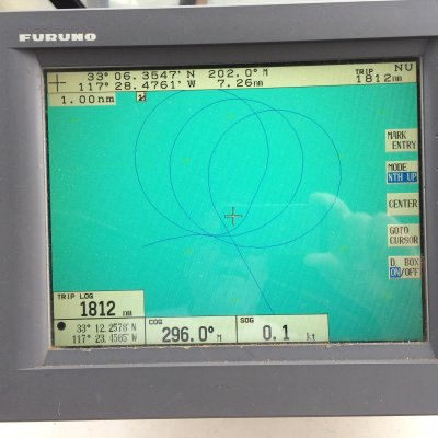
The pic below is from the first sea trial. The heading nav function worked perfectly right off. Lock in a heading and it held straight as an arrow.

Next test was to navigate a route. The algorithm calls for corrections at greater than 90 meter crosstrack error to return to the course line at a right angle. Values less than 90 return to the course line adjusting in the direction of the course line from a right angle at a rate of 1 degree per meter. In other words if you are 2 meters away you return to the course line at 2 degrees off the course bearing. This is so when you arrive to the course line you don't overrun it.

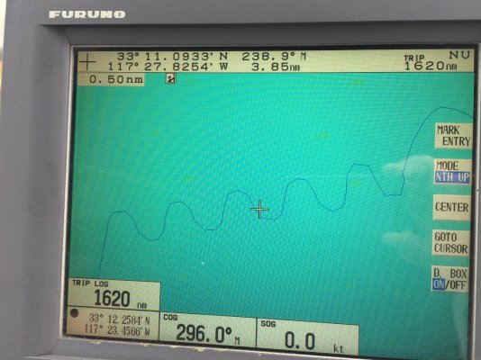
Long Story short is I specified radians instead of degrees in one statement so the autopilot thought it was always greater than 90 meters away from the course line and all corrections were applied to return at a right angle. I kind of freaked out at first but decided to let it steer to see what it was doing and it produced the sinusoidal course below. I messed with the gain towards the end and affected the shape. The course line is missing because I took the picture back at the dock after the course was cancelled.
 

Attachments

  • IMG_0169.jpg
    IMG_0169.jpg
    182.8 KB · Views: 65
I'm glad I'm not very smart and couldn't understand what was written, my son is an electrical engineer and I paid for his graduate degree from the University of Michigan so if I want to know what was said I can ask him. My question would be does it work on Zeus fly by wire drives which has the worst auto pilot ever invented. LOL
 
This is a sea trial of a function to navigate a circle of a given radius. The algorithm is based on a rate, time and distance equation applied to adjust the bearing continuously in order to hold the given radius. The same type of equation is applied to perform a 180 degree function. Since the function is based upon bearing and heading there is no central point to pin the radius so continuous circles are affected by current and wind producing a drifting circular pattern. This is not ground breaking but it does illustrate the navigation capability using an Arduino.

The first circle has a flat spot on one side this the result of my monkeying with the real time adjustment of the radius from .2 NM to 1 NM and then back to .2NM
 

Attachments

  • IMG_0230.jpg
    IMG_0230.jpg
    188.1 KB · Views: 84
The picture below is from a test route with multiple waypoints. The trasition into the segment at the bottom of the screen was quite fluid but the transition into the last segment produced an oscillation over the course line albeit the transition was a hard left. This is likely due to allowing too much rudder to be used and not receiving a position fix in time to make the necessary adjustment. If you need to make a 15 degree turn you can set the maximum rudder available at 3 degrees so the turn takes 5 times longer to complete. This would smooth out the turn and give more time for position fixes so we don't overrun the course line.

One thing to note is the code is watching for the GPRMB NMEA sentence. This provides the destination waypoint location for the active segment. The new segment is not sent until the current segment is completed so we will always drive through the current segment waypoint and have to find our way back to the new segment course line. Note When the new GPRMB arrives with the new end point it is followed by a GPRMC that contains the current destination that is our new start point.

There is a way to look ahead and that could be some interesting code to write. Perhaps we force the new location 90 meters before we arrive and start the transition early.
 

Attachments

  • IMG_0341.JPG
    IMG_0341.JPG
    190.5 KB · Views: 91
It's about like looking at an Iphone in direct sunlight. The screen does not have an anti-glare coating.

I believe technically it would not be considered sunlight viewable however it works quite well in daylight.

It is software dimmable with 16 increments. If you look at the snapshots I posted of the various screens one includes a slider for Rudder Gain and another slider for Dimming the Display. I anticipated these two functions to likely be the most accessed so I put them on their own page with minimal clutter.

If you message me your email address I'll send you the .ino file. I don't see a way to attach it here directly and it exceeds the size limit for a text file.

I would like a copy of the autopilot .ino file dhowes2003@yahoo.com
 
Pretty cool.

What are you using to drive the hydraulics?

A self learning PID algorithm can smack the XTE hunting into feet rather than 10's of yards.

Id caution you freely passing the code around. Garmins TR1 system was a garage shop effort and the developers didnt get rich giving it away.
 
Last edited:
Pretty cool.

What are you using to drive the hydraulics?

A self learning PID algorithm can smack the XTE hunting into feet rather than 10's of yards.

Id caution you freely passing the code around. Garmins TR1 system was a garage shop effort and the developers didnt get rich giving it away.

I developed circuitry that interfaces with the benmar 16B controller board to operate the pump. The TTL signals from the Arduino are converted into a compass signal that the Benmar interprets as left, right or neutral. Optionally I developed a circuit that will operate the pump directly as an add-on with the intention of disconecting the other Benmar components. For now I'm running with the former setup and have the option of switching between the new system or the old. As a side note, the Arduino works so well I haven't needed to go back to the old system but it does still work.

The attached jpg shows the TTL driver circuit circled in yellow. The circuit above is actually a duplicate of the original Benmar Controller. I designed it in Multisim so the pump is represented by light bulbs in the diagram. The second attachment shows the optional add-on board.
 

Attachments

  • BenmarCircuitUpdate11.JPG
    BenmarCircuitUpdate11.JPG
    172.1 KB · Views: 73
  • C1 (Medium).jpg
    C1 (Medium).jpg
    94.2 KB · Views: 74
This makes my tiny brain hurt.

I have a sitex system on board but it is missing the ECU. Sitex wants $500 for the ECU but I was thinking how hard could it be to build one or even adapt a raymarine ECU to work(more common).

I've been playing with arduino for the past few days hoping to build a multiplexer based on openpilot but keep hitting road blocks..
 

Latest posts

Back
Top Bottom