1Sailor
Veteran Member
- Joined
- Sep 28, 2012
- Messages
- 76
- Location
- USA
- Vessel Name
- Moondance
- Vessel Make
- Atlantic Prarie 30 LRC
Boat Battery problem Help!
OK - This is what I need help with:
There are two (2) banks of batteries on the boat - 1 House - 1 Engine start.
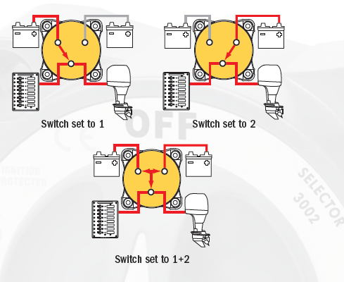
They each go to a 4 position Battery switch: Position 1 - Both - 2 - Off. The switch has been disconnected & tested for the propper continuity & working when cycled. There is no continuity between positions 1 & 2 and it’s off when in that position.
Here is the problem, it doesn’t matter which position the switch is in, both banks are connected to all loads. The house circuits can be used when in the “start” (position1) & the engine can be started from the “house” (Position 2). It’s as if the switch is always in the “Both” position.
Again the switch itself works and positions 1 - 2 - Both are isolated in the switch.
On the battery banks the Neutral terminals (“Minus” - ) are joined & then go to ground. I can’t see any other joining of the positive terminals.
Where do I start looking?
OK - This is what I need help with:
There are two (2) banks of batteries on the boat - 1 House - 1 Engine start.
They each go to a 4 position Battery switch: Position 1 - Both - 2 - Off. The switch has been disconnected & tested for the propper continuity & working when cycled. There is no continuity between positions 1 & 2 and it’s off when in that position.
Here is the problem, it doesn’t matter which position the switch is in, both banks are connected to all loads. The house circuits can be used when in the “start” (position1) & the engine can be started from the “house” (Position 2). It’s as if the switch is always in the “Both” position.
Again the switch itself works and positions 1 - 2 - Both are isolated in the switch.
On the battery banks the Neutral terminals (“Minus” - ) are joined & then go to ground. I can’t see any other joining of the positive terminals.
Where do I start looking?