Pictures of Er 77,78 mainship 34 mk1

The friendliest place on the web for anyone who enjoys boating.
If you have answers, please help by responding to the unanswered posts.

Alaskasbear

Veteran Member
Joined
Jun 10, 2016
Messages
58
Location
United States
Vessel Name
Slow Goin
Vessel Make
78 MS 34 Mk1
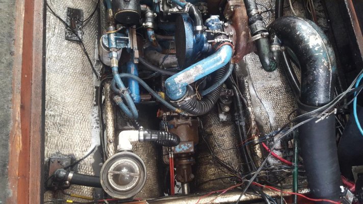
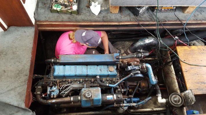
Does anyone have any pictures of Engine room a and different angles of the engine. Looking for what might be missing from mine and maybe ways I could improve on it such as deck plates down alongside the engine to protect transducers and make it easier to stand, rerouting of exhaust flange so it doesnt stick up so obnoxiously etc etc.
If you have some please post them. ALSO any pictures of the raw water pump and strainer assembly, battery layout. Looking to improve.
Here is what I'm working with now. Its a mess.
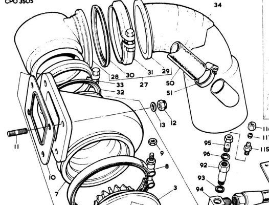
 

Attachments

  • 20160704_144304.jpg
    20160704_144304.jpg
    181.5 KB · Views: 228
  • 20160704_144252.jpg
    20160704_144252.jpg
    156.9 KB · Views: 218
  • 20160512_171503.jpg
    20160512_171503.jpg
    120.6 KB · Views: 215
If you are talking about the riser / elbow just before the water injection /mixer you want that as high as humanly and physically possible to prevent backflooding, it is good design and best practice as it is.

Your Batteries are where the generator would have been located, good place for the Batteries if you don't plan a genset.

The Racors on the aft bulkhead is where I have seen them on all I, II and II Mainships that I have been aboard, seems to be a good place for them as that's where the fuel lines from the saddle tanks naturally congregate

:socool:


rerouting of exhaust flange so it doesnt stick up so obnoxiously etc etc.
 
If you are talking about the riser / elbow just before the water injection /mixer you want that as high as humanly and physically possible to prevent backflooding, it is good design and best practice as it is.

Your Batteries are where the generator would have been located, good place for the Batteries if you don't plan a genset.

The Racors on the aft bulkhead is where I have seen them on all I, II and II Mainships that I have been aboard, seems to be a good place for them as that's where the fuel lines from the saddle tanks naturally congregate

:socool:

I Hadn't considered back flooding, very glad you brought that up. My racors are on the back and happy with them there. The battery mess I'm considering moving the engine battery up underneath the starboard and house to the port and making a cover for that hole over the shaft. I'm a pretty big guy and need room to maneuver . Dancing over batteries has been bumming me out. Just looking for other ideas to incorporate if its an improvement. Thank you Keys for the back flooding awareness. First boat I've ever been on that has a wet exhaust. All of them before had a stack.
 
This is my repowered 1978. Can take more if there is anything specific you're interested in.

I have a bank of four batteries on the starboard side just aft of the helm with an access port.

ForumRunner_20160721_223655.jpg


ForumRunner_20160721_223707.jpg
 
Nice looking ER. Doesn't look like chaos. I do see something I'm curious about. Is that like a walker air sep on your turbo? I'd love to keep those gases contained in the engine. They make everything dingy. I've already gone thorough once with degreaser and a pressure washer. About to do it again with more focus on the hull, bulkheads and stringers since i just finally got all the oil in the bilge mopped up. That project took 20 full sized absorbents.
 
Nice looking ER. Doesn't look like chaos. I do see something I'm curious about. Is that like a walker air sep on your turbo? I'd love to keep those gases contained in the engine.

It's a Racor unit, similar to the Walker Airsep.
 
The raw water strainer is exactly where mine was on my 78. When I repowered I relocated it on the starboard side of the engine (mid way) and ran the hose under the engine.
That got it out of my way for maintenance, etc.
I also ditched the 8D batteries and installed 2 group 27s (you could use grp 31s), one on each side of the engine forward just outside of the stringers. I built shelves for them out of plywood.
Again made for more body space.
 
perhaps I am missing something but that exhaust water inlet seems in exactly the wrong place, on the engine side of the riser.
 
ALSO any pictures of the raw water pump and strainer assembly, battery layout. Looking to improve.


Don't have any pics, but I think I remember having only a single 8D battery, located starboard of the engine, roughly underneath where one would stand at the lower helm. We had a genset, where your batteries are , and only once needed to run the genset/charger for a while before we could start the main engine. My fault, poor DC load management that day.

IF (IF!) a set of four (at least) 6V golf cart batteries -- series parallel, roughly 440 Ah -- would start your engine, believe I'd suggest you consider that as an option. Each individual battery lighter than a single 8D.

If you don't plan a genset, and even larger bank of GCs in the lazarette might be useful.

Or another configuration for consideration might be a single G31 start battery, maybe up near the engine, and a boatload of GCs in the lazarette for house loads.


Jeff's ER looks longer than what I remember about ours. And again, our genset was in the lazarette.

-Chris
 
I had a Walker Airsep, and I loved how it kept the ER clean. I would highly recommend either a Walker or similar to anyone with a vented crankcase.

:socool:
 
Jeff's ER looks longer than what I remember about ours. And again, our genset was in the lazarette.

-Chris

What generation was yours? I was thinking the same thing until I remembered his is a first generation.
 
perhaps I am missing something but that exhaust water inlet seems in exactly the wrong place, on the engine side of the riser.

I'm not sure what you mean. That is the stock exhaust riser i thought. Is the water inlet supposed to be on the other side of the hump?
OR is it on backwards?
 
Think I'm going to keep.the 8ds and move one to each side.to allow room for now and possibly a future genset reinstall. Wife and I talked about the 6 hatches and came up with the idea to add.brass piano hinges for every 2 sets narrowing it down to 3. And yes walker airsep or racor unit is going to be added. Thank you everyone for your responses. Raised questions I hadn't even considered. I am really curious about that exhaust riser though. Foing to try and find ot in the manual.
 
After doing some research i believe Bayview is correct and the inlet is on the wrong side of the riser. Not only is it on the wrong side it is injecting towards the engine leaving me to believe that the PO put it on backwards after changing the exhaust hose. Here is the picture of mine and also a picture i found on the web.(Don't mind the wife,she likes doing starters. Always has.) Someone correct me if I'm wrong or also chime in if I'm right in my assessment. Thank you Bayview for pointing this out.
 

Attachments

  • 20160705_172613.jpg
    20160705_172613.jpg
    156.1 KB · Views: 99
  • NS_Exhaust-Size_5F25_300.jpg
    NS_Exhaust-Size_5F25_300.jpg
    25.8 KB · Views: 345
At a minimum, you should take the exhaust riser off so you can see how the cooling water is injected. There may be some inner tubing that carries the injected water to the top of the elbow in such a way that the water is really not combined with the exhaust gases where it would appear. In other words, look inside closely before you just turn it around.
 
Really good point here:

There may be some inner tubing that carries the injected water to the top of the elbow in such a way that the water is really not combined with the exhaust gases where it would appear. In other words, look inside closely before you just turn it around.
 
Have you run the motor or looked at the turbo? If it is in fact backwards and was operated that way I would expect there to have been serious issues with raw water coming back into the turbo and motor.
 
:) Yes i planned on inspecting the riser and turbo qhen i take it off. Wouldnt be prudent to juat swap it .
 
Have you run the motor or looked at the turbo? If it is in fact backwards and was operated that way I would expect there to have been serious issues with raw water coming back into the turbo and motor.
1
Ran it up to temp 2 weeks ago before i had to head back up on the north slope for work. Sounded ok and fair amount of water came out the exhaust. But if the whole point of that riser is to block water from getting back to the engine,then everytime it gets shut off that last little splash would fall right back down and pool in the turbo correct? Causinh possible corrosion to the fins and maybe even the housing. So until I'm sure that it is mounted correctly I'm going to be proactive with it. I'm really not into problems on the water and trying to get it launched soon as possible after i get home in 2 weeks.
 
Actually that appears to me to be the wet elbow from a range 4 series Perkins.I have seen many of those. It is not original.
The original should look more like this:
 

Attachments

  • Capture2.JPG
    Capture2.JPG
    137 KB · Views: 45
Actually that appears to me to be the wet elbow from a range 4 series Perkins.I have seen many of those. It is not original.
The original should look more like this:

I was wondering about that because on the 3rd hatch back from the bow the insulation had been scooped out all the way to the wood to accommodate that elbow and it just did not look like anything a factory would do. But as I've said before this wet exhaust stuff is all new to me. If that is not the stock riser the that would make sense to hollow out the insulation to allow for the higher riser. Just not very professional. I sent you an email for the manuals. Thank you.
 

Latest posts

Back
Top Bottom