Battery Cable Size?

The friendliest place on the web for anyone who enjoys boating.
If you have answers, please help by responding to the unanswered posts.

Dixie Life

Senior Member
Joined
Feb 4, 2011
Messages
213
Location
USA
Vessel Name
Aku Uka
Vessel Make
43’ DeFever
Just started replacing all the batteries for my inverter. I had 6 gp31 AGM, changing to 8 6v trojans T-605. The two main feeder cables should stay the same; 2/0. But I need to recalculate the inner connect cables to series the two 6v together and the cable size for paralleling all the pairs together. Each battery has a 6v 210Ah rating. So the entire bank should equal 12v 840 Ah. Is there a formula for this? Thanks
 
Well, there isn't a formula, but there is a process for figuring the current load and wire size.


Depending on the wattage rating of your inverter, the maximum current that you can pull from the batteries is about 200 amps for a typical 2,000 watt inverter. That amperage is divided among 4 pairs of batteries or 50 amps each. It could be more, even 200 amps, depending on how you wire them in parallel: radial or daisy chain.


The series jumpers will all see a maximum of 50 amps. And both the parallel and series jumpers are short, maybe a foot or two each, so voltage drop is inconsequential. But I would use big enough wire so that any of the pairs can carry the full 200 amps, in case some of the batteries go bad.


Bottom line: I would use #2 for all jumpers. It can safely carry 200 amps. But if the batteries are in the hot engine room space, go with #1.


David
 
2/0 sounds small for a bank that size. What's the maximum rated continuous current for your inverter (the inverter's maximum current at lowest input voltage).The installation manual for the inverter should have that info and recommended cable sizes.
Anyway, the best practice is to use the same size throughout the system.
 
For the interconnects on the batteries we used 2/0 and from the batteries to the invertor we used 4/0 as per the manufacturer. Since we were using a lot of cable plus all the lugs, it was cheaper to buy everything in bulk when we made up the cables.

Calder's book, Boatowner's Mechanical and Electrical Manual: How to Maintain, Repair, and Improve Your Boat's Essential Systems, is good reference.
 

Attachments

  • Battery cables 001.jpg
    Battery cables 001.jpg
    171.2 KB · Views: 386
Hopefully one of the marine EEs will chime in.

When I did this, I ended up using 1/0 cables for the interconnects. I would have preferred to use 2/0, the same as the feeds to the panel, but really couldn't get 2/0 to actually fit.

To do it right, you need to calculate the voltage drop that you get from the cables from each of the connections between each 12v pair of batteries. You will have 3 12v pairs so add up the total length of the positive and negative cables between those pairs and plug that into a wiring calculator to figure out voltage drop. Your total voltage drop will be the total from your series connects and your run to your panel plus the run to ground. You want your total drop to be under 3%.

Plenty of calculators on the web. They will need total length of the circuit (some calculators take one way run and double it, others you need to provide the total circuit length), voltage (12v DC in your case), and the max amp draw.

What I did was to first calculate the voltage drop from my house bank to the panel with the 2/0 cables that I had. I then calculated the voltage drop from the series cables that were used in my bank (4 x 6v golf carts). In my case, the difference between using 2/0 interconnects and 1/0 interconnects was about .14%.

BTW, I think that the parallel interconnects in your bank (with 3 pairs) is going to be 1/3 of the total load. Again the series connection will carry the full load.

In short, I would first make sure that your existing 2/0 is adequate to give you under a 3% drop to your panel. Just because that is what is there doesn't mean that it is what it should be. Then figure out what will be necessary for your interconnects. The best way to do it is to make the series connections the same size and then downsize the parallel connectors. As I mentioned before, I didn't do this because I couldn't get the 2/0 to make the necessary connection in the tight space I had.

Finally, while you are doing this make sure that you have a fuse in the positive line within 7" of the battery bank terminal that is size appropriately to protect your wiring. I sized mine to protect the 1/0 interconnects, as that was the lightest gauge in the system.
 
For the interconnects on the batteries we used 2/0 and from the batteries to the invertor we used 4/0 as per the manufacturer. Since we were using a lot of cable plus all the lugs, it was cheaper to buy everything in bulk when we made up the cables.

Calder's book, Boatowner's Mechanical and Electrical Manual: How to Maintain, Repair, and Improve Your Boat's Essential Systems, is good reference.

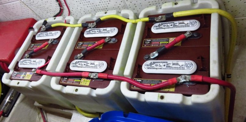
That is a very clean install Larry. The only thing I would wonder about is that you are pulling the positive and negative lead from the same end of your bank. I was always told that the positive and negative should come from opposite ends of the bank.
 
The AH rating of batteries in series is not additive, watts are but AH are additiv only in parallel.
 
Voltage is additive in series, amps in parallel. Dhays, you're right the feeders should be connected on opposite ends. But Larry has really got on my mad side; where did you get those white battery boxes. I've got the same boxes in black; didn't know there was a white opposition. LOL.
 
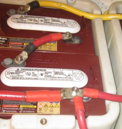
Larry, it looks like you have T605s; did you have any trouble getting the lugs to fit the stud height?
 
That is a very clean install Larry. The only thing I would wonder about is that you are pulling the positive and negative lead from the same end of your bank. I was always told that the positive and negative should come from opposite ends of the bank.

Thanks.

I agree that the positive and negatives should be at opposing ends of the bank so the voltage flows through the bank.

That picture wasn't very clear. I'll try this one. The upper right negative (yellow) cable is 4/0 and goes to the inverter. The lower right positive, (2/0) goes to the additional 4 T-105's on the other side of the engine room. The upper left negative (yellow) goes to the negative of the other battery bank on the other side. On the other bank, there is a positive 4/0 that goes to the inverter.

It's not an ideal set up but we have 10 batteries in our house bank. Trying to keep the cable runs short as possible was the goal.
 

Attachments

  • Battery cables 02.jpg
    Battery cables 02.jpg
    80.5 KB · Views: 318
Well, I thought my system was a little overkill; Mastervolt 200/4000 charger/inverter with a 840aH battery bank. But now all I can say is, Larry, you got it going on!
 
Larry, it looks like you have T605s; did you have any trouble getting the lugs to fit the stud height?

They are T-105's and yes I had problems with the lugs and the stud height.

If you go with Trojans and want bolt on terminals, I would suggest you go with the EHPT (embedded high profile terminal) post. The difference is the ability to stack more than 2-4/0 or 2/0 battery cables per post. With the standard post, the ELPT (embedded low profile terminal) you are limited to ~2. If you look at the lower right terminal, I have 1-4/0 and 2-2/0 lugs on the post. I would like to have a little more post height but it is what it is till I replace it. :)

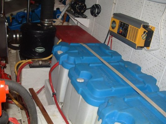
And the battery boxes were made by Blue Sea but are discontinued. We bought them 9 years ago from Fisheries Supply. There may still be a few out there.
 

Attachments

  • Battery Cables 002a.jpg
    Battery Cables 002a.jpg
    115.5 KB · Views: 347
This is a once in your ownership upgrade.

Since there is no downside , besides co$t the real fat 0-4 4-0 stuff whichever,, thick as your thumb is the best choice.

Yes its costly , but a whole boat load custom made becomes cheaper.

Sometimes bigger IS better.
 
The title of this thread really caught my eye since I just ran my first few feet of what seems like a mile of battery cable yesterday. The 1,240-AH house bank--8 6-volt AGMs--is just under the plywood. 4/0 isn't the easiest stuff to work with is it? :eek:

(Fred, your rationale is exactly what I've been telling myself.)

 
With a group of parallel banks (3 banks of 2 6V batteries for example), shouldn't each positive leg from each bank be sized to handle the entire load. That way bad banks can be removed from the parallel arrangement until replaced. I had to do that last year when one 6v in one bank went south. I took that bank out of the parallel arrangement until I could replace both batteries.

Tom
 
For the interconnects on the batteries we used 2/0 and from the batteries to the invertor we used 4/0 as per the manufacturer. Since we were using a lot of cable plus all the lugs, it was cheaper to buy everything in bulk when we made up the cables.

Calder's book, Boatowner's Mechanical and Electrical Manual: How to Maintain, Repair, and Improve Your Boat's Essential Systems, is good reference.


Where did you find those battery boxes?
 

Attachments

  • Picture 028a.jpg
    Picture 028a.jpg
    96.3 KB · Views: 152
  • batteries port side, new a.jpg
    batteries port side, new a.jpg
    185.1 KB · Views: 146
Last edited:
as a rough estimate...

the inverter has a >= 90% efficiency, so 4000/.9 = 4444.5 watts input at full load.

4444.5/12.6 = 352.7 Amps @ 12.6 volts
4444.5/12.2 = 364.3 Amps @ 12.2 volts
That is the current you need to support to run the inverter at full power with ZERO voltage drop.

4444.5/12.2 = 364.3 Amps @ 12.2 volts
4444.5/11.8 = 376.6 Amps @ 11.8 volts
That is the current you need to support to run the inverter at full power with 3% voltage drop.

It would be a real feat to lose only 3% at that current level. The main culprits are the wire size, the quality of the crimp and it's connection to the wire, and the quality of the connection to the battery posts.
 
It would be a real feat to lose only 3% at that current level. The main culprits are the wire size, the quality of the crimp and it's connection to the wire, and the quality of the connection to the battery posts.
user_offline.gif


And dont forget the class T fuse that should be in the circuit.


It would be a real feat to lose only 3% at that current level. The main culprits are the wire size, the quality of the crimp and it's connection to the wire, and the quality of the connection to the battery posts.
user_offline.gif


And dont forget the class T fuse that should be in the circuit.


I went with a semiconductor fuse for my 3000 watt inverter as it was cheaper than class T.

Fuses Unlimited Semiconductor Fuse - 300 Volts

I don't think any such power supply fuse can actually save any inverter, the fuse is only for the wires. Inverter cascade failure of the mosfets happens just too fast.
 
I don't think any such power supply fuse can actually save any inverter, the fuse is only for the wires. Inverter cascade failure of the mosfets happens just too fast.[/QUOTE]

That is true. I went the same route as you.
 
Blue Sea has an ampacity calculator/app. Put in your parameters and it tells you the required cable size.
 
A semiconductor fuse might protect a semiconductor, like a mosfet, if each individual mosfet had its own individual semiconductor fuse. In an inverter exists multiple banks of mosfets. In mine I have 8 banks and in each bank 4 mosfets. A timer chip turns banks on and off using a mosfet driver. But I really doubt even an individual fuse can protect any mosfet unless the fuse is way underrated compared to mosfet capability, and designers will run these mosfets right close to the max power edge.

So since each mosfet is maybe rated 90 amps max, when too much demand or heat or age on the mosfet or age on capacitors, or the mosfet drivers shorts out, then the mosfet fails to turn off. Then all sorts of bad things happen, like this is an internal short. Mosfet is not designed to stay on flowing huge amps, but still the supply semiconductor fuse is 350 amps so it just wont blow. Then one mosfet goes, it brings down the others, then the bank is in a continual conduction phase, wont turn off, so they get so hot they burn. This can destroy all the other mosfet banks, yet the main power supply fuse never blows.

You want a quick fuse, cause you don't want to overload the inverter power wire in a short for a long time, whats the point, the wire will just get hot waiting for the fuse to open, meanwhile the inverter might even start a fire. Although if your there you will just smell a lot of nasty electrical smoke. I had an inverter burn, and it kept conducting current till I turned off the battery switch. The amp draw through a few burned mosfets, was not enough amp flow to blow the inverter fuse. The fuse is just in case the supply wire shorts together.

Most fuses blow with much higher amps than what is their rating, and they blow slow. So for inverter, you want that super fast fuse. A slow fuse is just bad idea there.

A starter motor you want a regular, not a super fast fuse. If you put a super fast fuse on a engine starter, a good chance it will blow open since the instantaneous amp flow is going to be very high.

I do not have any breaker-fuses on any engine starters, but I read ABYC is now recommending them.
 
Last edited:
A fuse technically isn't designed to protect the MOSFETs/scr's/diodes etc. Its job is to keep the wires from catching on fire when load faults.
while a semiconductor fuse is fast its not fast enough by itself. Generally when they talk about protecting they mean it will blow at a current level the device can withstand for the time it takes the fuse to blow. In order for that to happen there has to be done filters in the circuit to slow down the rise time of the current

Designed properly the semiconductor fuse can protect a multibank inverter but it had to have been designed accordingly.
 
A good inverter has a load detection circuit and shuts itself down on overloads, so then self protects.

Thing is all electronics eventually seem to fail and self destruct regardless of the kind intentions of their circuit designers.

Today even with the intense circuit complexity, I think they like them to eventually fail so the customer comes back to get another, 'newer and improved' design. Keeps the business going.
 
Last edited:
Since my original post went from cable size to MOSFETs and inverters, let me throw another fly into the ointment. Now that I have my new bank setup I will need to reprogram the settings in the inverter. I intend to set the cutoff at about 60% rather than 50% of discharge. By reducing the depth of charge the new batteries should last longer. This is done on the MV system by setting the cutoff voltage for the bank. A 12v setting is suppose to be around 55%. Is there a formula the calculate the voltage for exactly 60%?
 
Since my original post went from cable size to MOSFETs and inverters, let me throw another fly into the ointment. Now that I have my new bank setup I will need to reprogram the settings in the inverter. I intend to set the cutoff at about 60% rather than 50% of discharge. By reducing the depth of charge the new batteries should last longer. This is done on the MV system by setting the cutoff voltage for the bank. A 12v setting is suppose to be around 55%. Is there a formula the calculate the voltage for exactly 60%?
Trouble with using voltage as an indicator of state of charge is it cannot be under load and should be at rest for a period of time.

I'd leave it as an emergency cutoff, raising it may give you a false cutoff need.

Use a better indicator of status than an inverter voltage cutoff....even guessing based on time and averaging loads is probably as accurate if you try a little.
 

Latest posts

Back
Top Bottom